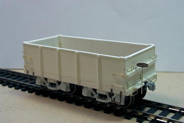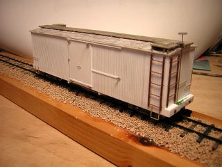
Scratchbuilt double-sheathed boxcar in styrene and stripwood. Scale/gauge is Sn2. Trucks are Tichy HO archbar with a narrowed bolster. Wheelsets are from MDC HOn3 passenger trucks. Couplers are Kadee #714. Ties are Mt. Albert 5"x5"x5' sugar pine. Rail is code 55 Micro-Engineering pre-weathered.
In order to make use of commercially available mechanisms and wheelsets, Sn2 appropriates HOn3 components (in North America, at least). This makes the measured gauge between railheads 26.45" instead of Maine's actual 24". The difference of .038" in width is ignored in the interest of expediency. Some modellers add an extra few inches to the length of the 5'-0" ties in order to preserve the visual proportions.
(EDIT 2015)
In response to some (persistent) prodding, I am including a complete re-write of the unpublished article from 2007. I ended up painting the car for a fictional line I was going to call "Cumberland & York"...
A Sandy River & Rangeley Lakes Inspired Boxcar in Sn2
As a crew member for an On2 layout construction project, I've recently been exposed to an incredible wealth of two-foot gauge prototype photos as well as some wonderfully detailed models of rolling stock, motive power, and structures. I found the low-slung wooden cars very pleasing in size and proportion and began to get that unmistakable feeling of wanting one (or more) to call my own. My own area of interest centres around S-scale standard and 42" gauge in the mid 1950 timeframe, so I thought it would be interesting (and probably more appropriate for me) to build a car in Sn2 to demonstrate the relative differences in size of equipment.
The Sn2 Homepage (
http://www.narrowtracks.com/Sn2/index.htm) and the Sn2_Trains discussion group at "Yahoo!" (
http://groups.yahoo.com/group/Sn2_Trains/) gave me a good start with plenty of scale-specific information. I knew I would need to obtain at least trucks and couplers from commercial sources and it turns out that the Tichy HO archbar (#3002) and Kadee HOn3 couplers (#714) are the current components of choice for freight cars. Luckily my local hobby shop had both of these items in stock when I paid them a visit the next day. The HO archbar sideframes just happen to work out to a 4'-0" wheelbase in S-scale.
I dug through my boxes of "previously enjoyed" magazines looking for plans of the Maine 2' equipment. Fortunately, Jim Dunlop has made a significant contribution of drawings in 1/4" scale to The NG&SL Gazette over the years. Many railroads started out with only a small fleet of box and flat cars to carry their goods, so I thought it only fitting to choose a Sandy River & Rangeley Lakes boxcar in the #121-145 series as my first attempt (pg. 59, Sept/Oct 1990 Gazette). A quick trip to the photocopier (set at 75%) gave me enough reference sheets to begin work.
In order to pass the time at local train shows, I've been taking along a small project and an assortment of tools to get some modelling work done while I sit at one of the tables in our group's display area. Show attendees and fellow exhibitors always take the time to ask what I'm up to, and offer their ideas and advice. This time I took the boxcar drawings (reduced to 3/16"=1'-0") and enough Evergreen Styrene sheets and strip stock to make a start on the underframe and car sides.
Styrene is the material that I am most comfortable working with, even though I have enjoyed some success using brass and wood for a few projects. As I get better at building models, I'll probably try to make more items from robust metal and realistic wooden raw materials. Styrene just doesn't seem to lend itself well to locomotive frames or spindly wooden trestles. The proper tools and techniques for working with styrene are documented in many publications (including Evergreen's own comprehensive book), so I'll only mention how I've done something if I'm fairly certain that it's an obscure approach.
From the drawing I calculated the vertical siding width at 3" but the only scribed sheet stock I had represented a 3.2" width (Evergreen Styrene #2050, .050" spacing, .020" thick). I did not have access to a prototype car to actually count the number of boards and, realistically, there would have been variations in different batches of boards from the finishing mills at the time. Knowing that it would be unlikely for the average viewer to count the number of boards on the model, I quickly relented and made use of the on-hand material to make the most of the time I had set aside for this project.
By the end of the day I had the underframe, sides, and ends of the car formed and assembled to my liking. I decided to model the car with the doors closed, so the car sides are solid sheets with the doors applied on top, rather than having cut-outs for the door openings. This gave more gluing surface for the relatively thin (.020") stock I was using. The interior walls were also braced with longitudinal strips of styrene (about .080"x.080") to stiffen them and help keep everything square. The high-roofed, well ventilated hall we were in made applying the styrene solvent (Ambroid Pro Weld) much more bearable than my somewhat cramped and stuffy work area at home. During the show I also took time to answer questions from the attendees, scanned the various vendor tables looking for bargains, and found a quiet corner to enjoy some food and drink with acquaintances who are also involved in the hobby.
After returning home I undertook the job of narrowing the Tichy trucks. Here I ran into a bit of a snag as I miscalculated the amount I needed to cut off the first truck bolster's ends. I did manage to properly cut the second bolster and assemble the truck. In the case of the incorrect bolster I simply used a suitable section of square styrene for the bolster component. Wheelsets were taken from an MDC # 02929 passenger car package. The finished trucks are reasonably free rolling and well aligned, but there is some doubt in my mind as to their ability to stay together under long-term use with only CA (Zap-a-Gap) as an adhesive. It remains to be seen if these modified trucks will require installation of some mechanical fasteners for greater durability.
#3002 HO heavy duty Arch Bar truck (Tichy)
stock axle length
.995" long (this would be end-to-end on the supplied Tichy HO axle)
stock truck bolster
.960" long
#02929 HOn3 passenger truck (MDC)
HOn3 axle length
.722" long
New (cut down) truck bolster length:
.995 - .722 =
.273" total material to be removed from truck bolster
.960 - .273 =
.687" new overall length of truck bolster
.273 divided by 2 =
.1365" to be removed from each end of truck bolster
.687 + .1365 =
.824" for setting your caliper (see below)
Set and lock the jaws of a vernier caliper at .824" (you do have a vernier caliper, right?). Using one end of the stock bolster as a guide, lightly scribe the other end of the bolster with the caliper jaw tip. Flip the bolster around and repeat the process on its other end . Cut the excess off one end with a razor saw and file up to the scribed line, ensuring that you are square both vertically and horizontally. Check that the overall length of the truck bolster is now .824". Cut the excess off the other end with a razor saw and file up to the scribed line, again keeping it nice and square. Set and lock the calipers at .687" and check the overall length. For sanity's sake, check the distance from the edge of the kingpin hole to each end of the truck bolster and see that they are equal to each other (in this case it was ~.297") otherwise the wheelsets will not be centred under the car. Press the nylon bearings into the Tichy journal boxes. Carefully hold the wheelsets in place and, using your other two hands, glue the side-frames to the modified truck bolster. Please note that if you are using different wheelsets than those supplied with the MDC truck (such as NWSL or Kadee HOn3) you must substitute their axle length for that of the MDC (.722" in this case) in the calculations above.
 |
| FIGURE 1: Scribing the bolsters |
[SEE FIGURE 1]
Checking back on the Sn2 Homepage I noted the car underbody needed to be a scale 18" (9/32") from the railhead. The body bolsters were cut and adjusted several times before I was happy with how the car was sitting on the trucks. Not having any track laid at this point, I simply added 1/32" to the height I measured from the flat work surface to account for the depth of the wheel flanges. The body bolsters were drilled and tapped for #00-80 machine screws. Some interference occurred between the floor beams and sideframes during truck rotation, so the two small bolt-head castings at the top of each of the Tichy truck sideframes were filed off to eliminate this problem (these small details cannot be seen in any event).
 |
| What happens when you mess up the first bolster... |
Assembling a #714 coupler can be a bit of a chore for someone, like me, who is possessed of large hands; not impossible but often quite frustrating. Once I managed the feat, small styrene blocks glued flush between the two centre sills provided a flat surface to mount and fasten the coupler boxes. These blocks were drilled #60 for the self-tapping screws that were provided with the couplers
[SEE FIGURE 2]. Magnetic trip pins were not installed, per the recommendation on the Sn2 Homepage. Switching chores will require the use of the ubiquitous bamboo skewer or jeweller's screwdriver for uncoupling. Recently, Sergent Engineering (
http://www.sergentengineering.com/) has released a die-cast, pre-assembled, HO scale coupler in a narrow draft gear box (part #EN87A). It appears to be the perfect size for use in Sn2 and is more realistic in both appearance and operation than the #714. It does not offer delayed action uncoupling, so care must be taken to ensure that sidings requiring switching are placed within easy reach of the layout edge if you choose to adopt this product.
 |
| FIGURE 2: Adding the coupler box |
The roof was created as a separate sub-assembly to simplify the construction overall process for me. The real roofs were covered in tin squares, tarred at the joints. Duplicating this look using heavy paper cut in 24"x24" squares with a grey weathering wash turned out fairly well but I would make the next attempt with thick aluminium foil
[SEE FIGURE 3].
 |
| FIGURE 3: "Tin" squares made from heavy paper |
Roofwalk supports are triangular cross-sections sliced from a wedge-shaped piece of Mt. Albert scale lumber, formed using a #11 X-acto blade clamped (at the same angle as the roof) to an aluminium block on my worktable. The strip lumber was drawn backwards through the blade several times to produce the wedge
[SEE FIGURE 4]. I also used this improvised tool to thin the roofwalk boards to about 1/2 their original bulk, as I did not have any thin stock on hand. The boards were all treated to a few applications of "Weather It" liquid. Following the placements indicated on the reference drawing, the wedges were attached to the roof using Weldbond glue and allowed to dry overnight. Once dry, the roof was inverted and all of the wedges were lightly sanded simultaneously on a large piece of fine sandpaper taped to a flat surface. This corrected any humps in the array of wedges so that the roofwalk boards would lie flat when attached
[SEE FIGURE 5].
 |
| FIGURE 4: The bevelled stripwood and its chopped wedges |
 |
| FIGURE 5: The basic roof assembly |
Grabs and stirrups were formed from Detail Associates .012" brass wire and .015"x .024" bar stock respectively. On the L-shaped grabs, Detail Associates #2206 diesel eyebolts were used to anchor the corners. Grandt Line # 4019 turnbuckles and #4031 queenposts were employed underneath the car. Truss rods were formed from .012" brass wire and glued in place with CA. Truss rod bolts with square washers set in the end beams are Tichy #8082. Ladders are shortened Grant Line #4020 offerings
[SEE FIGURE 6].
Grandt Line #5040 HO scale brake rigging was recommended to complete the underframe details, but I must respectfully disagree with this option. It would be far better to make up the few necessary pieces from scratch, as there are no components in this package that compare favourably to the photographic evidence I currently have access to. One brake compromise I had to make (for the moment) was the use of a Tichy #3003 HO brake wheel; I simply could not find a suitable 5-spoke, S-scale wheel in any of the catalogues I was able to refer to. From a typical viewing angle, none of the undercarriage brake rigging is visible to the operator; you need to have the model much nearer to eye-level to see it. As this was never intended to be a contest-quality model, I limited myself to a modified cylinder/reservoir from the Grandt package
to enhance the silhouette for the time being.
 |
| FIGURE 6: Roofwalk and brakewheel added |
The car sides, ends, and trucks were brush painted Badger Model Flex Light Tuscan Oxide Red (#16-14). One of my assumptions is that an early 1900s, somewhat marginal 2' gauge operation would be unlikely to possess a full shop with spray painting facilities. Therefore my Sn2 models would be painted using a regular brush, rather than with an airbrush. Over this red I applied several thin washes of Polly Scale Engine Black (#414290). The bright silver MDC wheelsets were treated to a dunking or two in Blacken-It; the wheel treads were then lightly polished with fine steel wool (wheelsets with a narrower tread width would definitely improve the overall appearance of the model). The underframe, roof, and trucks were covered in a thicker wash of Engine Black. The roof looks as if some rough patches and sharp edges of the tin sheeting are showing through the black paint. The roofwalk boards were left unpainted to reduce their slipperiness in wet weather conditions. Woodlands Scenics MG702 letters and MG708 numbers dry-transfers were applied, and Bragdon Enterprises "Ash" powder was brushed on to dull the finish
[SEE FIGURE 7].
 |
| FIGURE 7: Cumberland & York #124 |
The original Gazette drawing raised a few questions which I felt necessary to have the answers to in order to complete this car. More detailed drawings and some prototype photos were obtained and, coupled with questions asked of the experts on various discussion forums, these yielded the remaining secrets. It is evident from photographic records that this series of cars (121-145) had significant variation in construction details and features. I am unsure if these variations were introduced at the point of construction or resulted from rebuilding over time. A single side and end view of one or even two cars would be woefully inadequate to describe the full range of these variations.
Why did I choose to scratchbuild a car that is one of the few examples for which a kit is already available? Well, I learned more about real railroad car construction, tried out some new methods of assembly and painting, and got to know many new people in the hobby. In the end, I am fairly pleased with how the finished piece turned out. If you don't want to build everything from scratch, Train & Trooper sell appropriate Maine narrow gauge equipment in S-scale and have gone to the immense trouble and expense of importing several beautiful brass Forneys to supplement their range of structure and rolling stock kits (EDIT 2015: sadly, T&T are no longer operating).
What would I do differently on future Sn2 projects? Aside from more planning and careful study of each prototype, I'll have to collect and/or create a dedicated set of detail parts specific to 2' applications. The door details (hangers, brackets, latches) are particularly annoying, as scavenging bits from several casting packages (in O, S, and HO scales) leaves you with a bunch of incomplete part sets for your other models, and raises the per-Sn2-car price considerably. I now have several packages of Grandt Line #4001 car hardware and #6 door hangers that are missing bits; a very wasteful approach. Were I to desire a fleet of these cars I would certainly make "master" subassemblies, such as the doors complete with all details, and cast several dozen of each in resin. I would also plan to install a piece of brass bar stock or steel key stock in the centre sill area to add some weight to the assembly. Styrene by itself is simply too light to guarantee good tracking when switching cars during an operating session.
Once I get on with hand-laying any significant amount of track, there will be a need for some roller gauges and jigs for turnout frogs. Fortunately, these will be simple to fabricate from either brass or aluminium. I will also take the time to create a jig to allow me to accurately mill off the extra bits of the Tichy bolsters to get the right width of trucks "first time - every time". In the meantime, a couple of short lengths of code 55 rail laid with Micro Engineering "micro" spikes on 5"x5"x5' ties will do for display purposes. Sn2 track standards reflect HOn3 specifications; this results in 2' gauge in S being nearer to 26". There has been some discussion online of adding 2" to the tie length to compensate for any visual difference.
While I have been fortunate enough to obtain one of the T&T inside-frame 2-4-4 Forneys, I do intend to construct at least one other locomotive. My aim will not be to duplicate any particular Maine 2-foot unit, but rather to capture the general look and feel as closely as possible. I prefer the appearance of the Forney type, so another 2-4-4 or a 0-4-4 might be just the ticket. A recently located HOn3 Forney should provide a decent frame and boiler to attach a larger cab and details, if I can get a new motor fitted without major surgery. However, a 2-6-2 may be more straightforward to construct given the ready availability of MDC HOn3 Consolidation chassis and running gear. Resin domes and stacks, along with laser-cut cab components are available from Jerry Wilson (see the Manufacturers link at the Sn2 homepage) to compliment the MDC conversions.
My thanks go out to John Hitzeman, Trevor Marshall, and many, many others for their time and assistance with this project.