I used to own a draughting board. I made it in the Wood shop at high school. Most of a 3/4" thick, 4'x6' sheet of cabinet grade ply ended up as the top. The frame and legs were made from 5/4 poplar, with through mortises and lapped mitres. Based on the finished results, the teacher asked me to make him a table, too (a great compliment, frankly). Everything from deck design to charcoal sketches and Dungeon maps happened on this spacious worktop. Many years later, it was sold to a fellow who did technical illustrations. I vaguely regret the decision to do so, but I'm sure it did the job for him.
One of my classmates had made a smaller "artists" table with a tilting top which was equally adept at doing small draughting jobs (up to C size). I inherited this board when he passed away and enjoyed using it as a sketching surface for several years. A fairly talented watercolour artist was thrilled to become the new owner of this table as her primary work space; I'm sure its creator approves.
Fast forward a few years; I was required to take a course on technical drawings as part of the machining programme at a local college. It was supposed to be "Interpretation of Engineering Drawings" which, as the title suggests, is an analytic exercise. However, by the time this course was to begin, it had somehow magically transformed into "Introduction to Basic Drafting" (sic). Back to the drawing board, indeed. Surprisingly, I was able to locate my cache of supplies from high school, avoiding an extra cost but not the disappointment at this ham-fisted re-jigging of the curriculum.
The college was in the middle of an upgrade effort at the time and, as luck would have it, I was able to obtain one of their old, parallel-equipped boards for homework completion. A good size and more convenient than using my venerable T-squares. Upon finishing this programme, the board went on to a college girl undertaking Interior Design. I hope it serves her well.
While I have some facility with CAD software (both 2D and 3D) there are still many tasks which are made more pleasant by having an actual, physical board to putter about upon. My better half recently located a portable board of decent size which I quickly commandeered and re-assembled. It is equipped with a sliding parallel and is meant to be used while resting on another table top, making it dead easy to put away when not needed (a triumph compared to having a 4'x6', limited purpose table sitting in the room). Once again the pencils & erasing shields are out...
Seems I can't really live without a draughting board of some kind. I guess I'm just old fashioned.
An informal journal of various model railway projects.
I neither accept nor assume any responsibility for the results of actions by persons attempting to duplicate my efforts regardless of the methods employed. Always wear proper safety equipment and follow manufacturer's instructions for tool and material usage.
Showing posts with label design. Show all posts
10.04.2012
3.24.2012
approaching sector four
The sector plate is taking shape on the Port Rowan layout. We were able to install the supports, cut the MDF deck, secure it to the supports and align the plate with the approach track.
The pivot point needs to be drilled, and the bushings installed in the MDF plate and deck. This will happen next week at our upcoming work session. Once the hole is drilled, we can use a jig saw to cut a curve on the end of the sector plate itself.
Almost 100% certain how the sector plate will be driven. A threaded rod and handle will move a follower pin under the plate, driving the plate to align 1 of 4 tracks. I just need to locate an appropriate anti-backlash nut to make it happen smoothly.
The pivot point needs to be drilled, and the bushings installed in the MDF plate and deck. This will happen next week at our upcoming work session. Once the hole is drilled, we can use a jig saw to cut a curve on the end of the sector plate itself.
Almost 100% certain how the sector plate will be driven. A threaded rod and handle will move a follower pin under the plate, driving the plate to align 1 of 4 tracks. I just need to locate an appropriate anti-backlash nut to make it happen smoothly.
3.11.2012
stop and go
The bead spinner sits idle. Did it work? Oh yes, it threw them everywhere with verve and gusto. Is it quiet? Yes, can barely detect that it's running. Is it user-friendly? No, it needs a speed control and some guards for the moving parts. Another project on hold for the moment.
On the railroad front, the trestle bents were all assembled during the last work session. Making a jig sped things up and ensured consistent results. I'd do it differently were I to do it again; making some refinements to the jig to aid cutting of the pilings, etc. The trestle looks great and there will be a riverbed raising party soon to match it all to the height of the pilings. See the progress at the Lynn Valley Trestle entry on Trevor's blog.
2.05.2012
clearance, Clarence
Can't seem to create much slip between two pieces of K&S brass tubing. Just too close in fit. Even spun the smaller one inside the larger one with a shot of Brasso using a cordless drill to see if I could lap some gap into the assembly. It moves slightly more freely, but not as much as I'd like.
Now, had I wanted a tight fit without fasteners or adhesives, no amount of mucking about would have produced it.
This is in pursuit of a slightly different turnout control for a layout project. The stands are from Sunset Valley, and they will actuate a FastTracks Bullfrog under the points. The Bullfrog has it's detent spring removed, and the two devices will be connected together using Sullivan R/C aircraft cables. The SV switch stands operate just like the real thing, and are sized for use with garden railway equipment.
Now, had I wanted a tight fit without fasteners or adhesives, no amount of mucking about would have produced it.
This is in pursuit of a slightly different turnout control for a layout project. The stands are from Sunset Valley, and they will actuate a FastTracks Bullfrog under the points. The Bullfrog has it's detent spring removed, and the two devices will be connected together using Sullivan R/C aircraft cables. The SV switch stands operate just like the real thing, and are sized for use with garden railway equipment.
11.28.2011
re musings
It may be obvious to some that the subject of modular, portable layouts weighs heavily on my mind.
I have been posting my thoughts on the matter and these, while not definitive or exhaustive, represent the lessons learned from a few years of effort (and numerous observations) in the field.
The most recent posting are, as yet, very rough. I wanted to get them out depsite incompleteness. Sometimes it helps to actually see what one is thinking about in order to better organise thoughts.
I will be editing these entries to add more content, links, and (hopefully) diagrams to clarify and expand on various points.
I have been posting my thoughts on the matter and these, while not definitive or exhaustive, represent the lessons learned from a few years of effort (and numerous observations) in the field.
The most recent posting are, as yet, very rough. I wanted to get them out depsite incompleteness. Sometimes it helps to actually see what one is thinking about in order to better organise thoughts.
I will be editing these entries to add more content, links, and (hopefully) diagrams to clarify and expand on various points.
11.19.2011
modular musings, part 3 (electrical)
If you can't get the control signals or power to the locomotives, all the mechanical construction effort is for nought. I will discuss electrical aspects with DCC in mind.
You need to have robust connectors, able to manage the high current draws:
i.e. Anderson, Cinch-Jones, trailer...
Each have their beneifts and drawbacks. Any one of them can be "bad" if they are not used properly.
What about power districts? Modern sound equipped locos can draw significant amounts of power, and having a short at one end of the modular layout should not disrupt activity at the other end.
- maximum track buss length for each booster should be less than 50'
Employ 'unique' connectors at the interfaces to prevent mix-ups. Throttle buss, track buss, and accessory power buss should NOT be able to be connected to each other. Throttle buss cabling is usually something like a Telco RJ12, so that's not too difficult to keep apart. However, you must bear in mind that there are 'straight through' and 'crossover' versions of typical Telco and Datacom cables - beware mixing them in a daisy-chain!
http://www.tonystrains.com/technews/utp.htm
http://www.vif.com/users/r-rhurlbut/On30-Modules/GM/03.pdf
If you choose to use something like an Anderson Powerpoles for both the track and accessory wiring harnesses, ensure that you use different dovetailed plug arrangements for each.
Hermaphrodite connections saves 1/2 your material costs for electrical hardware, and is especially useful in Free-mo 180° end-for-end flip situation.
Make troubleshooting provisions from the beginning. Nothing takes more time than tracing an electrical fault. Employing quick disconnects, terminal blocks, and nicely dressed colour coded wiring will help but remember that each break in the wire (for a connector, plug or whatever) is another potential point of failure. Also, DO NOT make something that only one person can fix, and DO NOT rely on proprietary "gizmo" solutions.
- buzzer box
Radio Shack buzzer + 2 alligator leads for track laying
see "Testing" section of http://www.wiringfordcc.com/track.htm
- buss run AWG
Heavy, stranded, Landscape wire (designed for outdoor use, thick insulation, high amp/low volt)
- track buss taps
3M IDC Suitcase connectors,
Telegraphers "tap" slice (aka Western Union joint in some circles)
- track feeders AWG
light, short (less than 6"), solid
Keep accessory power draws OFF the DCC buss! DCC is for loco power & layout communication only! If you're wondering why you loco is behaving erratically, maybe you should disconnect the 'welding flicker' and 'telegraph sounder' from your track buss. Electrical noise coupled-in to the command signals is BAD. The decoders determine what to do through edge-detection in the DCC signal. Don't add to the noise by tacking on a bunch of animated elements. A DC or AC wall-wart adaptor, or an old PC power supply (with PWRGOOD mod) will run all your online accessories.
- Loconet buss termination
A properly sized resistor at the end of the track buss will help reduce or eliminate ringing & overshoot of the DCC signal. Early Tsunami decoders were susceptible to overvoltage/spikes, causing premature failure in some cases. Spikes can hit over 22V on a DCC system set for 16V output.
- communication buss
With the advent of full-duplex radio, it may be that you don't need this on the layout. However, there is no need for the expense of radio throttles at yard locations. Adding a few plug-in throttle jacks won't hurt, and may help to reduce radio interference at larger shows.
If you are going to add throttle jacks to your modules, put two at opposite diagonal corners of the module set. This ensures that, whatever the orientation, there are jacks at even spacings around the layout. You won't have far to move if you need one.
- DCC vs DC
will depend on # of simultaneous locos & operators
- getting power to the layout
anti-trip mats to run power cable through, do not daisy chain extension cords, multi-tap AC cords
- turnout power
local adaptors, low volt AC buss, low volt DC buss, Tortoises vs solenoids (CD, SwitchWitch or Circuitron), servos (TamValley, AneModel)
- turnout control
DCC throttles, momentary buttons, toggles, computer, hand thrown, Pete's panel
- cables
making your own, 3-pair telco, x-over vs straight through, proper crimping tools
- test equip
RRAMp meter, Telco cable tester, hooking up UP5 LEDs, buzzer box, Digitrax LT1
sites for further study:
http://www.wiringfordcc.com/
http://en.wikipedia.org/wiki/Electrical_termination
Circuitron "Snapper" cap-discharge solenoid driver:
http://www.circuitron.com/index_files/Tortoise.htm
Tractronics "SwitchWitch" stall motor driver:
http://users.rcn.com/weyand/tractronics/articles/articles.htm
RRAmp meter for DCC testing:
http://www.tonystrains.com/technews/rrampmeter.htm
series 302 Cinch connectors:
http://ca.mouser.com/ProductDetail/Cinch/P-302H-CCT/?qs=sGAEpiMZZMvlX3nhDDO4ACp%252b9pCER64wSkfV%2Fj%2FSjMo%3D
Anderson Powerpole connectors & accessories:
http://www.powerwerx.com/
R/C servomotor controllers for turnouts:
http://www.tamvalleydepot.com/
http://www.anemodel.com/product.html
IDC Scotchlok connectors:
http://tinyurl.com/bwrr4rw
Misc:
http://www.saskschools.ca/curr_content/paasurvey/elec/lesson5/lesson5.html
http://www.amhobby.com/products/tech/generic/wire_sizes.html
http://zone.ni.com/devzone/cda/tut/p/id/3073
http://www.dccwiki.com/Wire_sizes_and_spacing
You need to have robust connectors, able to manage the high current draws:
i.e. Anderson, Cinch-Jones, trailer...
Each have their beneifts and drawbacks. Any one of them can be "bad" if they are not used properly.
What about power districts? Modern sound equipped locos can draw significant amounts of power, and having a short at one end of the modular layout should not disrupt activity at the other end.
- maximum track buss length for each booster should be less than 50'
Employ 'unique' connectors at the interfaces to prevent mix-ups. Throttle buss, track buss, and accessory power buss should NOT be able to be connected to each other. Throttle buss cabling is usually something like a Telco RJ12, so that's not too difficult to keep apart. However, you must bear in mind that there are 'straight through' and 'crossover' versions of typical Telco and Datacom cables - beware mixing them in a daisy-chain!
http://www.tonystrains.com/technews/utp.htm
http://www.vif.com/users/r-rhurlbut/On30-Modules/GM/03.pdf
If you choose to use something like an Anderson Powerpoles for both the track and accessory wiring harnesses, ensure that you use different dovetailed plug arrangements for each.
Hermaphrodite connections saves 1/2 your material costs for electrical hardware, and is especially useful in Free-mo 180° end-for-end flip situation.
Make troubleshooting provisions from the beginning. Nothing takes more time than tracing an electrical fault. Employing quick disconnects, terminal blocks, and nicely dressed colour coded wiring will help but remember that each break in the wire (for a connector, plug or whatever) is another potential point of failure. Also, DO NOT make something that only one person can fix, and DO NOT rely on proprietary "gizmo" solutions.
- buzzer box
Radio Shack buzzer + 2 alligator leads for track laying
see "Testing" section of http://www.wiringfordcc.com/track.htm
- buss run AWG
Heavy, stranded, Landscape wire (designed for outdoor use, thick insulation, high amp/low volt)
- track buss taps
3M IDC Suitcase connectors,
Telegraphers "tap" slice (aka Western Union joint in some circles)
- track feeders AWG
light, short (less than 6"), solid
Keep accessory power draws OFF the DCC buss! DCC is for loco power & layout communication only! If you're wondering why you loco is behaving erratically, maybe you should disconnect the 'welding flicker' and 'telegraph sounder' from your track buss. Electrical noise coupled-in to the command signals is BAD. The decoders determine what to do through edge-detection in the DCC signal. Don't add to the noise by tacking on a bunch of animated elements. A DC or AC wall-wart adaptor, or an old PC power supply (with PWRGOOD mod) will run all your online accessories.
- Loconet buss termination
A properly sized resistor at the end of the track buss will help reduce or eliminate ringing & overshoot of the DCC signal. Early Tsunami decoders were susceptible to overvoltage/spikes, causing premature failure in some cases. Spikes can hit over 22V on a DCC system set for 16V output.
- communication buss
With the advent of full-duplex radio, it may be that you don't need this on the layout. However, there is no need for the expense of radio throttles at yard locations. Adding a few plug-in throttle jacks won't hurt, and may help to reduce radio interference at larger shows.
If you are going to add throttle jacks to your modules, put two at opposite diagonal corners of the module set. This ensures that, whatever the orientation, there are jacks at even spacings around the layout. You won't have far to move if you need one.
- DCC vs DC
will depend on # of simultaneous locos & operators
- getting power to the layout
anti-trip mats to run power cable through, do not daisy chain extension cords, multi-tap AC cords
- turnout power
local adaptors, low volt AC buss, low volt DC buss, Tortoises vs solenoids (CD, SwitchWitch or Circuitron), servos (TamValley, AneModel)
- turnout control
DCC throttles, momentary buttons, toggles, computer, hand thrown, Pete's panel
- cables
making your own, 3-pair telco, x-over vs straight through, proper crimping tools
- test equip
RRAMp meter, Telco cable tester, hooking up UP5 LEDs, buzzer box, Digitrax LT1
sites for further study:
http://www.wiringfordcc.com/
http://en.wikipedia.org/wiki/Electrical_termination
Circuitron "Snapper" cap-discharge solenoid driver:
http://www.circuitron.com/index_files/Tortoise.htm
Tractronics "SwitchWitch" stall motor driver:
http://users.rcn.com/weyand/tractronics/articles/articles.htm
RRAmp meter for DCC testing:
http://www.tonystrains.com/technews/rrampmeter.htm
series 302 Cinch connectors:
http://ca.mouser.com/ProductDetail/Cinch/P-302H-CCT/?qs=sGAEpiMZZMvlX3nhDDO4ACp%252b9pCER64wSkfV%2Fj%2FSjMo%3D
Anderson Powerpole connectors & accessories:
http://www.powerwerx.com/
R/C servomotor controllers for turnouts:
http://www.tamvalleydepot.com/
http://www.anemodel.com/product.html
IDC Scotchlok connectors:
http://tinyurl.com/bwrr4rw
Misc:
http://www.saskschools.ca/curr_content/paasurvey/elec/lesson5/lesson5.html
http://www.amhobby.com/products/tech/generic/wire_sizes.html
http://zone.ni.com/devzone/cda/tut/p/id/3073
http://www.dccwiki.com/Wire_sizes_and_spacing
modular musings, part 2 (mechanicals)
The enemy is variation. Avoid dimensional softwood lumber for portable applications; continual changes in temperature and humidity wreak havoc with it. You may be well served to seal any wood to limit the effects of moisture (something like sanding sealer or shellac, perhaps); beware of acrylic coatings, the painted surfaces can stick to each other after being clamped together.
Goals are fast and repeatable setup, and optimal strength-to-weight ratio. Heading straight to "lightweight" can lead to fragile construction. It won't matter if it's light if the first time you clamp it to another module the endplates flex or rip right off, or you drop it and it turns into a pile of kindling.
Track expansion. Attach rails firmly above the interface (soldered to PCB tie plate or brass screws), and allow for rail gaps somehwere inside the MODULE confines.
PC board tie plates (Free-mo)
http://www.bnm-hobbies.com/store/index.php?main_page=product_info&cPath=20_21&products_id=19
Thought points:
- (Simon's) profile blocks to ensure consistent rail height at each joint.
- A single socket directly below the main line. Fit pin as needed to align to next section or module.
- Minimum number of tracks crossing any joint.
- Solid vertical member under the subroadbed itself to prevent sagging.
- Track must be 90°to both the horizontal and vertical planes at each INTERFACE.
(an INTERFACE differs from a SECTION JOINT, as a MODULE differs from a SECTION)
- Maple Leaf Mafia aluminium CNC frames
Avoid using porous material in the subroadbed, especially if you use the water soluble method of applying ballast or scenery near the track. Absorbed water tends to swell and distort the material. Using soap or alcohol to cut surface tension just makes it easier for the water to get in.
90° ends are critical everywhere. Setup & check your chop saw carefully. Verify the alignment with a proper try square and the cut-flip-match method of ensuring 90°. Cut matching sides and ends in pairs (at least). Mark what they are for. Clamp up and assemble frame pieces on a flat surface. Check 90° Horiz & Vert again. Get the frame dead square! Apply top and/or corner gussets. Route off edges of top with laminate trimmer bit (if it has a flat deck).
The primary mechanical goal is to ensure accurate track alignment across the joints. The secondary goal is an even fascia for the sake of appearance. Scenic continuity can be accomplished through application of loose material along the joint after assembly. Keep some spice tins or shaker bottles of each type of material handy in your toolbox for shows. Accuracy can be a problem if many people are making their own modules; everyone executes cutting and fitting tasks at their own skill level.
Low density self-adhesive foam weatherstrip can be used to take up the eventual (hopefully minimal) gapping at the joints. This stops loose scenic material placed on the joint for exhibition from falling through to the floor. Do not use thick or high density foam, you don't want to make the gap bigger (foam tape the perimiter of the end board to create even compression).
Pierre Oliver, master carpenter and owner of Elgin Car Shops, recommends cabinet grade plywood ripped to appropriate widths for all framing members. There are no voids or inclusions, and the multiple plies offer greater dimensional stability.
Creating the boards: Take the ripped plywood and make a frame. Add braces across the width. Stanley corner brackets or gussets should be applied to ensure squareness and add screw locations. Keep clamping & cable area at MODULE and SECTION joints clear.
Fastening the MODULES or SECTIONS together: Quik-Grip clamps. Try to clamp immediately below the track itself. C-clamps need more clearance for the lever arm. Loose bolts, washers & wing nuts - adds to part count and things that can go missing. T-nuts (or threaded inserts) and furniture bolts can strip out or seize at inopportune times.
quick-attach adjustable legs - single pipe with foot, interchangable, retained (bayonet, squeeze fit, spring pin)
http://home.online.no/~bjornrl/modulebuild.htm
Lee Valley dowel pins, leg feet:
http://www.leevalley.com/en/hardware/page.aspx?p=40145&cat=3,43586,43588,40145
http://www.leevalley.com/en/hardware/page.aspx?p=41865&cat=3,40993,41283
patternmakers pins, etc.:
http://www.stationroadbaseboards.co.uk/menu_fittings.htm
make an accurate drilling jig, use drill bushings, store safely:
http://carrlane.com/catalog/index.cfm/27025071F0B221118070C1C512D020609090C0015482013180B041D1E173C3B285351435E
More thought points:
- dropping the egg crate example
- French cleat vs ledger board
- protect root of cleat (cover/scraper?)
- legs/supports
- tool-less height adjustments
- height adjustment at the top of the leg
- pads to protect floors (gymnasiums, churches, etc.)
- crowd barriers
- concrete post bases + ABS 'tees' with rope on a spindle (Jim)
Goals are fast and repeatable setup, and optimal strength-to-weight ratio. Heading straight to "lightweight" can lead to fragile construction. It won't matter if it's light if the first time you clamp it to another module the endplates flex or rip right off, or you drop it and it turns into a pile of kindling.
Track expansion. Attach rails firmly above the interface (soldered to PCB tie plate or brass screws), and allow for rail gaps somehwere inside the MODULE confines.
PC board tie plates (Free-mo)
http://www.bnm-hobbies.com/store/index.php?main_page=product_info&cPath=20_21&products_id=19
Thought points:
- (Simon's) profile blocks to ensure consistent rail height at each joint.
- A single socket directly below the main line. Fit pin as needed to align to next section or module.
- Minimum number of tracks crossing any joint.
- Solid vertical member under the subroadbed itself to prevent sagging.
- Track must be 90°to both the horizontal and vertical planes at each INTERFACE.
(an INTERFACE differs from a SECTION JOINT, as a MODULE differs from a SECTION)
- Maple Leaf Mafia aluminium CNC frames
Avoid using porous material in the subroadbed, especially if you use the water soluble method of applying ballast or scenery near the track. Absorbed water tends to swell and distort the material. Using soap or alcohol to cut surface tension just makes it easier for the water to get in.
90° ends are critical everywhere. Setup & check your chop saw carefully. Verify the alignment with a proper try square and the cut-flip-match method of ensuring 90°. Cut matching sides and ends in pairs (at least). Mark what they are for. Clamp up and assemble frame pieces on a flat surface. Check 90° Horiz & Vert again. Get the frame dead square! Apply top and/or corner gussets. Route off edges of top with laminate trimmer bit (if it has a flat deck).
The primary mechanical goal is to ensure accurate track alignment across the joints. The secondary goal is an even fascia for the sake of appearance. Scenic continuity can be accomplished through application of loose material along the joint after assembly. Keep some spice tins or shaker bottles of each type of material handy in your toolbox for shows. Accuracy can be a problem if many people are making their own modules; everyone executes cutting and fitting tasks at their own skill level.
Low density self-adhesive foam weatherstrip can be used to take up the eventual (hopefully minimal) gapping at the joints. This stops loose scenic material placed on the joint for exhibition from falling through to the floor. Do not use thick or high density foam, you don't want to make the gap bigger (foam tape the perimiter of the end board to create even compression).
Pierre Oliver, master carpenter and owner of Elgin Car Shops, recommends cabinet grade plywood ripped to appropriate widths for all framing members. There are no voids or inclusions, and the multiple plies offer greater dimensional stability.
Creating the boards: Take the ripped plywood and make a frame. Add braces across the width. Stanley corner brackets or gussets should be applied to ensure squareness and add screw locations. Keep clamping & cable area at MODULE and SECTION joints clear.
Fastening the MODULES or SECTIONS together: Quik-Grip clamps. Try to clamp immediately below the track itself. C-clamps need more clearance for the lever arm. Loose bolts, washers & wing nuts - adds to part count and things that can go missing. T-nuts (or threaded inserts) and furniture bolts can strip out or seize at inopportune times.
quick-attach adjustable legs - single pipe with foot, interchangable, retained (bayonet, squeeze fit, spring pin)
http://home.online.no/~bjornrl/modulebuild.htm
Lee Valley dowel pins, leg feet:
http://www.leevalley.com/en/hardware/page.aspx?p=40145&cat=3,43586,43588,40145
http://www.leevalley.com/en/hardware/page.aspx?p=41865&cat=3,40993,41283
patternmakers pins, etc.:
http://www.stationroadbaseboards.co.uk/menu_fittings.htm
make an accurate drilling jig, use drill bushings, store safely:
http://carrlane.com/catalog/index.cfm/27025071F0B221118070C1C512D020609090C0015482013180B041D1E173C3B285351435E
More thought points:
- dropping the egg crate example
- French cleat vs ledger board
- protect root of cleat (cover/scraper?)
- legs/supports
- tool-less height adjustments
- height adjustment at the top of the leg
- pads to protect floors (gymnasiums, churches, etc.)
- crowd barriers
- concrete post bases + ABS 'tees' with rope on a spindle (Jim)
11.18.2011
a traumatic idea...
...for a portable exhibition layout.
It's always a bother to drag legs, skirting, and the boxed-up sections of your exhibition layout out, using a hand cart or simply lugging the dead weight of it all. Often you have to make two trips back and forth to the vehicle.
How about using an ambulance gurney frame as the basis of the layout? The rolling chassis would fold up as you shoved it into the back of your van or pickup, and unfold as you dragged it out. Then it would be easy to roll it from the parking lot up to the venue and into your assigned spot. Just lock the wheels and drop some skirting around the edge of the frame to cover the chassis.
The frame would support an approximately 24" x 72" layout. Plenty for an HO or OO shunting plan, or an N terminus or single industrial complex. You should even be able to make a nice O14 or O16.5 scene in this footprint.
But where would you buy a used gurney?
It's always a bother to drag legs, skirting, and the boxed-up sections of your exhibition layout out, using a hand cart or simply lugging the dead weight of it all. Often you have to make two trips back and forth to the vehicle.
How about using an ambulance gurney frame as the basis of the layout? The rolling chassis would fold up as you shoved it into the back of your van or pickup, and unfold as you dragged it out. Then it would be easy to roll it from the parking lot up to the venue and into your assigned spot. Just lock the wheels and drop some skirting around the edge of the frame to cover the chassis.
The frame would support an approximately 24" x 72" layout. Plenty for an HO or OO shunting plan, or an N terminus or single industrial complex. You should even be able to make a nice O14 or O16.5 scene in this footprint.
But where would you buy a used gurney?
11.12.2011
tinkering, thinkering
I have been mulling over the idea of a "participatory event", hopefully assisted by the local hobby shop. The concept is to pre-package enough plywood and track for anyone to build a T-Trak module in N scale. It wouldn't be a contest so much as a way to develop modelling skills and encourage a bit of diversity within the area's exhibition landscape. At the end, all modules would come together in a group display. Perhaps a popular vote would be held, but certainly a reward of some kind would be dispensed to all participants.
Many newcomers to the hobby are overwhelmed by the idea of a large, home layout. Some intermediate modellers stall in their thought processes. Long-timers may wish to dabble in something else; "a change is as good as a rest", it is said. City dwellers and young people relying on public transit find it difficult to move large modules. All of these people would (likely) benefit from interaction with like-minded modellers. A small project like this would offer a kickstart or development platform.
T-Trak offers an incrementally-sized base to build upon, starting at about a foot square. The material requirements for baseboards are minimal; no legs and only a simple box frame. Track requirements are similarly light; parallel (at each end) Kato Unitrack components. It may be possible to provide a kit of essential parts for as little as $25. Modules are connected together on, and supported by, the ubiquitous 30" high folding-leg tables lurking at exhibit & conference halls.
The event organiser would have to provide four corners and one straight section in order to guarantee that any number of participants could be provided for during the culminating exhibition. Tying-in with a large local train show would be the best course of action; many modellers would be in attendance anyway, and the display could be seen by the largest number of visitors. I would recommend the "33mm spaced centre" version of the T-Trak build, so that many of Kato's accessories could be incorporated without modification.
Kato's track products are, frankly, some of the best in the hobby. My recent experiments with their N Unitrack sections have proved pleasant and trouble-free. I was able to have a long-idle locomotive running on a loop of track in mere minutes. While the pre-ballasted track sections are not preferred for many advanced techniques used by "serious" hobbyists, they provide a good looking basis for reliable and consistent running - minimising disappointment and maximising the fun factor; crucial elements for newcomers to the hobby.
Many newcomers to the hobby are overwhelmed by the idea of a large, home layout. Some intermediate modellers stall in their thought processes. Long-timers may wish to dabble in something else; "a change is as good as a rest", it is said. City dwellers and young people relying on public transit find it difficult to move large modules. All of these people would (likely) benefit from interaction with like-minded modellers. A small project like this would offer a kickstart or development platform.
T-Trak offers an incrementally-sized base to build upon, starting at about a foot square. The material requirements for baseboards are minimal; no legs and only a simple box frame. Track requirements are similarly light; parallel (at each end) Kato Unitrack components. It may be possible to provide a kit of essential parts for as little as $25. Modules are connected together on, and supported by, the ubiquitous 30" high folding-leg tables lurking at exhibit & conference halls.
The event organiser would have to provide four corners and one straight section in order to guarantee that any number of participants could be provided for during the culminating exhibition. Tying-in with a large local train show would be the best course of action; many modellers would be in attendance anyway, and the display could be seen by the largest number of visitors. I would recommend the "33mm spaced centre" version of the T-Trak build, so that many of Kato's accessories could be incorporated without modification.
Kato's track products are, frankly, some of the best in the hobby. My recent experiments with their N Unitrack sections have proved pleasant and trouble-free. I was able to have a long-idle locomotive running on a loop of track in mere minutes. While the pre-ballasted track sections are not preferred for many advanced techniques used by "serious" hobbyists, they provide a good looking basis for reliable and consistent running - minimising disappointment and maximising the fun factor; crucial elements for newcomers to the hobby.
5.24.2009
to thine own self...
Solid reference material like this article on Byron Henderson's blog, will get most people moving down the right track in terms of their own layout planning. Note: make sure you follow along to the subsequent parts of the article series to get full benefit of the material; it's well worth the time invested in reading it.
Having spoken to a number of people (of various experience levels) about their layout plans, I've noticed one very important factor. The more honest you are with yourself with respect to an analysis of your own abilities, disposable cash, and overall goals, the more likely you are to build a satisfying layout. This seems like a "duh" point at first but, having now seen the results of the planning and execution of several layouts - and getting the back-story of a few more layouts during operating sessions, a definite pattern is emerging.
Those people who ignored finances (I never have enough money for gas, but I'll need 33 extremely rare brass locomotives for this plan to work) skill level (despite the fact I can't tie my own shoes, I'm sure I'll be able to cut my own offset mitre gears for an N scale Climax one day) or goals (I'm a confirmed and grumpy loner but my design requires 7 to 9 tightly-knit operators to make the sessions work) have generally built layouts that make them unhappy to own and operate.
Notice I've used the qualifier "satisfying" instead of "good". A good layout is not necessarily one that receives critical acclaim for its clever use of materials or 100% adherence to prototype track arrangement, but it certainly is one that brings you joy to use and is not a unbearable burden on your time, a regrettable use of your space, or an onerous money-pit that can't be finished without depriving yourself of food & clothing.
Having spoken to a number of people (of various experience levels) about their layout plans, I've noticed one very important factor. The more honest you are with yourself with respect to an analysis of your own abilities, disposable cash, and overall goals, the more likely you are to build a satisfying layout. This seems like a "duh" point at first but, having now seen the results of the planning and execution of several layouts - and getting the back-story of a few more layouts during operating sessions, a definite pattern is emerging.
Those people who ignored finances (I never have enough money for gas, but I'll need 33 extremely rare brass locomotives for this plan to work) skill level (despite the fact I can't tie my own shoes, I'm sure I'll be able to cut my own offset mitre gears for an N scale Climax one day) or goals (I'm a confirmed and grumpy loner but my design requires 7 to 9 tightly-knit operators to make the sessions work) have generally built layouts that make them unhappy to own and operate.
Notice I've used the qualifier "satisfying" instead of "good". A good layout is not necessarily one that receives critical acclaim for its clever use of materials or 100% adherence to prototype track arrangement, but it certainly is one that brings you joy to use and is not a unbearable burden on your time, a regrettable use of your space, or an onerous money-pit that can't be finished without depriving yourself of food & clothing.
9.12.2008
portable ponderings, part 1
Over time, I've been involved in many discussions regarding transportable (and fixed) layout construction. This has, of course, generated more than a few pro-and-con debates over the various approaches that can be taken to create the displays.
It might help if the process of creating the display were treated in a more methodical manner than is often employed. Each of the factors listed below have an effect on the finished product. Some consideration should be given to each point in turn.
WHO will be building the display?
- expertise
- free time
- workspace
- fabrication tools
- vehicles
- budget
WHY are you creating the display?
- to promote your aspect of the hobby (scale, gauge, era,
location, theme)
- to enjoy the fellowship of like-minded hobbyists
- to operate your equipment
WHAT would be desirable features of the display?
- quick setup
- reliable operation
- low maintenance
- easy to build
- easy to transport
HOW will these goals be obtained?
- thorough planning
- standardisation
- simplified electrical & mechanical connections
- robust wiring
- solid framing
- good trackwork
- minimum tool requirements
WHAT will you need to achieve the goals?
- jigs & fixtures
- setup diagrams
- setup checklists
- equipment checklists
- electrical connections either clearly coded OR
only one mating plug per interface
- one type of fastener for everything
- spares!
Further thoughts and discussion points will be posted on each of the above items as time permits. You may wish to reference the Layout Design Primer for in-depth analysis of a variety of topics.
It might help if the process of creating the display were treated in a more methodical manner than is often employed. Each of the factors listed below have an effect on the finished product. Some consideration should be given to each point in turn.
WHO will be building the display?
- expertise
- free time
- workspace
- fabrication tools
- vehicles
- budget
WHY are you creating the display?
- to promote your aspect of the hobby (scale, gauge, era,
location, theme)
- to enjoy the fellowship of like-minded hobbyists
- to operate your equipment
WHAT would be desirable features of the display?
- quick setup
- reliable operation
- low maintenance
- easy to build
- easy to transport
HOW will these goals be obtained?
- thorough planning
- standardisation
- simplified electrical & mechanical connections
- robust wiring
- solid framing
- good trackwork
- minimum tool requirements
WHAT will you need to achieve the goals?
- jigs & fixtures
- setup diagrams
- setup checklists
- equipment checklists
- electrical connections either clearly coded OR
only one mating plug per interface
- one type of fastener for everything
- spares!
Further thoughts and discussion points will be posted on each of the above items as time permits. You may wish to reference the Layout Design Primer for in-depth analysis of a variety of topics.
1.29.2007
1/2"n2 chassis
There is a space 1.74" x 3.48" clear under the tram body to permit the installation of a powered chassis. The only item that can stick up into the "control cabin" on the loco is the electric motor itself. None of the wheels, gears, or sprockets can protude above the floorplate.
The plan is to drive a single rigid axle using a 59:1 Falhauber gearhead motor through a set of 90ยบ helical gears. Ideally, the second tilting axle will be connected to the first using Serv-o-link Delrin sprockets and chain. The helical gears will need to be enclosed in a small gearbox to keep them in proper mesh and reduce any strain on the motor shaft and/or bearings.
Drive wheels should be slightly larger than 14" diameter, but that will depend on the minimum size of sprockets that can be used. Bearing boxes will be hung on the ends of the axles. One set will be fixed, the other will be free to move in their vertical axis.
The plan is to drive a single rigid axle using a 59:1 Falhauber gearhead motor through a set of 90ยบ helical gears. Ideally, the second tilting axle will be connected to the first using Serv-o-link Delrin sprockets and chain. The helical gears will need to be enclosed in a small gearbox to keep them in proper mesh and reduce any strain on the motor shaft and/or bearings.
Drive wheels should be slightly larger than 14" diameter, but that will depend on the minimum size of sprockets that can be used. Bearing boxes will be hung on the ends of the axles. One set will be fixed, the other will be free to move in their vertical axis.
8.05.2006
the LGB Forney project
Some time ago, I was asked if I could narrow an LGB Forney from 45mm gauge to 32mm gauge, in order to better represent the 2' gauge appearance of the prototype. I said yes, but the project languished on my workbench for a lot longer than I ever intended. I did manage to locate a suitable, smaller diameter motor and make measurements (and some plans) for the conversion, but never actually got to it for various reasons.
So this weekend everything came together for a start. I've narrowed both wheelsets on the rear truck to the proper gauge, and am proceeding with the manufacturing of a new truck bolster. Removing 13mm width on the trailing truck and power chassis is going to be a chore; but seeing if the loco manages to walk on it's new "high heels" is going to be something else entirely.

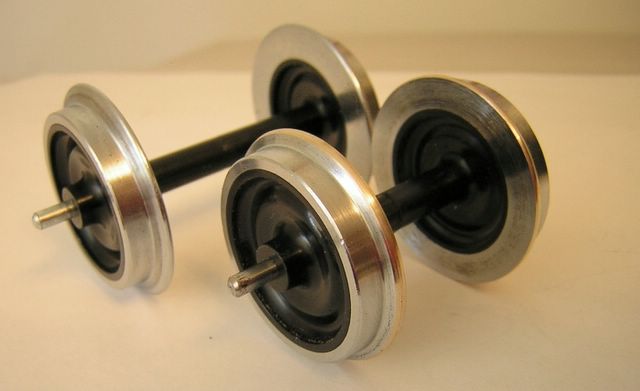
Shown here are one each of the modified and stock wheelsets. Note the flange depth on the narrowed set has been reduced to about .072" from .120".

Here is the truck with the new (brass) bolster partially completed. Holes for the sideframe attachment screws and kingpin still need to be drilled at this point.
So this weekend everything came together for a start. I've narrowed both wheelsets on the rear truck to the proper gauge, and am proceeding with the manufacturing of a new truck bolster. Removing 13mm width on the trailing truck and power chassis is going to be a chore; but seeing if the loco manages to walk on it's new "high heels" is going to be something else entirely.

Shown here are one each of the modified and stock wheelsets. Note the flange depth on the narrowed set has been reduced to about .072" from .120".

Here is the truck with the new (brass) bolster partially completed. Holes for the sideframe attachment screws and kingpin still need to be drilled at this point.
Subscribe to:
Posts (Atom)