If you decide to use commercial track products for your layout or modules, BEFORE you start laying these on the baseboard and pinning or gluing them down, CHECK the gauge of each and every piece with a proper NMRA (or other regulatory body's) measuring tool.
Seriously.
I have experienced at least a half dozen separate instances where the commercial product's rail are not in gauge, and can't be corrected. The latest instance involved removing a turnout from a ballasted right of way while making a minimum of mess. Not fun.
Every turnout, every crossing, every piece of sectional or flex track needs to be checked before it is installed. Items that are not in gauge need to be returned to their place of purchase as defective. These items are produced in batches and can vary as enviromental changes and mechanical wear occur.
While you're at it, verify the electrical arrangements of each turnout's point & stock rails with a continuity tester. This is especially important in DCC applications where the optimal situation is to have each point rail the same polarity as its adjacent stock rail to prevent shorting when wheelset's back-to-back distance might be a tad tight. I have had two turnouts where the short rail section after the frog had become isolated from the rest of the route (the wire bond underneath was broken) creating a dead spot.
Save yourself some pain and check first.
Showing posts with label module. Show all posts
Showing posts with label module. Show all posts
2.04.2013

2.01.2013
a-musing rehash
I've been meaning to update my series of posts "modular musings" on this blog for quite some time.
Recent events and discussions with other modellers reveal that portable layout design, DCC systems, and electrical wiring (in general) are all topics that could stand some review and discussion.
Over the next few weeks, I will try to update these posts with more observations and links to relevant information.
Stay tuned...
Recent events and discussions with other modellers reveal that portable layout design, DCC systems, and electrical wiring (in general) are all topics that could stand some review and discussion.
Over the next few weeks, I will try to update these posts with more observations and links to relevant information.
Stay tuned...
timing is everything
Lots of stuff going on lately.
Model Railroadish stuff, mostly.
A trip to the Amherst Railway Society's big train show in Springfield, MA offer ample chance to blow one's mind with possibilities. Add to that a heaping goodie basket of new things from the various vendors...
Travelling with local traction modeller extraordinaire Roger Chrysler was a real treat; I'd be more than happy to repeat the process for any train show I can think of.
However, unexpectedly, I had to debug the S Scale Workshop's layout on Friday afternoon. Due to time constraints, I was attending the show for Saturday only, and had not anticipated being able to enter the show grounds ahead of time. Through sheer luck & good timing I was in the same building as the layout late in their setup phase. Workshop member Andy Malette of MLW Services spotted me while I chatted with Jeff Adam of Motrak Models. Andy hauled me back to the layout to see what was going on.
The DCC system was giving the group fits. I found several things wrong over the course of the next hour or so:
The first three issues were isolated and sorted out fairly quickly by halving the layout's busses until the faults revealed themselves. The last item could not be readily repaired as that Tortoise is part of a complex control panel comprised of momentary pushbuttons and LED route indicators that doesn't lend itself to tracing wires unless that module set is laying on its side; which was not practical at that point in the setup.
One issue I should have dealt with was to ensure that the Command Station was centrally located along the track buss. The layout was about 80' in length this time around thanks to some excellent new modules built by member John Johnston. Our habit has been to hook the Command Station into the buss about 8' from one end. Not such a big deal when the layout is in the 40-50' range, but it gets much worse as track buss lengthens. Next time...
In the end, the layout was operational for the weekend. I was able to come back on Saturday after lunch and, while the rest of the crew ran trains, chat with the general public and other modellers who viewed the modelled scenes and trains. Some great questions were asked and many compliments were made.
It came as a pretty big surprise to the crew when the Amherst Railway Society's committee stopped by at about 4 PM and awarded us "Best in Show - Layouts" for 2013. We are certainly honoured to be recognised in this manner. Needless to say, spirits were running high for the rest of the weekend.
Model Railroadish stuff, mostly.
A trip to the Amherst Railway Society's big train show in Springfield, MA offer ample chance to blow one's mind with possibilities. Add to that a heaping goodie basket of new things from the various vendors...
Travelling with local traction modeller extraordinaire Roger Chrysler was a real treat; I'd be more than happy to repeat the process for any train show I can think of.
However, unexpectedly, I had to debug the S Scale Workshop's layout on Friday afternoon. Due to time constraints, I was attending the show for Saturday only, and had not anticipated being able to enter the show grounds ahead of time. Through sheer luck & good timing I was in the same building as the layout late in their setup phase. Workshop member Andy Malette of MLW Services spotted me while I chatted with Jeff Adam of Motrak Models. Andy hauled me back to the layout to see what was going on.
The DCC system was giving the group fits. I found several things wrong over the course of the next hour or so:
- three custom made, twisted-pair (Cat5?) LocoNet cables were causing the throttle buss to spasm
- one LocoNet UP5 panel was not daisy-chained correctly
- a rail gap had closed up at one turnout, shorting the track buss
- a damaged Tortoise had been replaced but the frog power routing had been compromised, shorting the track buss when the points were aligned for the main.
The first three issues were isolated and sorted out fairly quickly by halving the layout's busses until the faults revealed themselves. The last item could not be readily repaired as that Tortoise is part of a complex control panel comprised of momentary pushbuttons and LED route indicators that doesn't lend itself to tracing wires unless that module set is laying on its side; which was not practical at that point in the setup.
One issue I should have dealt with was to ensure that the Command Station was centrally located along the track buss. The layout was about 80' in length this time around thanks to some excellent new modules built by member John Johnston. Our habit has been to hook the Command Station into the buss about 8' from one end. Not such a big deal when the layout is in the 40-50' range, but it gets much worse as track buss lengthens. Next time...
In the end, the layout was operational for the weekend. I was able to come back on Saturday after lunch and, while the rest of the crew ran trains, chat with the general public and other modellers who viewed the modelled scenes and trains. Some great questions were asked and many compliments were made.
It came as a pretty big surprise to the crew when the Amherst Railway Society's committee stopped by at about 4 PM and awarded us "Best in Show - Layouts" for 2013. We are certainly honoured to be recognised in this manner. Needless to say, spirits were running high for the rest of the weekend.
11.24.2012
smooth moves
Recently I was helping my dad wire up a 2-track staging yard for his O-16.5, Welsh inspired portable layout. Dad already had the yard built and attached, so I just packed up my VOM and other electrically necessary tools for the job. The wiring itself was easy.
The staging yard is a removable shelf that attaches to the back of the quarry section of the layout. Trains enter and leave the sceniced portion through a hole in the backdrop.
The intent is to be able to park a couple of short trains off scene, and selectively power one track or the other. The layout is controlled with a Stapleton walkaround DC throttle so a simple on-off-on toggle did the trick in the new yard. A flying lead equipped with Anderson PowerPole connectors brought power from the quarry section.
The entrance to the yard was via a curve ladi across the edge joint and, due to some dimensional assumptions, there was a short slope from the backdrop down into the yard tracks. The included 18" radius section lead directly into the point end of a Peco insulfrog turnout.
And this is where the trouble all started.
One section of rail at the frog end of the "previously enjoyed and slightly shortened" Peco turnout had an intermittent electrical connection. In addition, the points are powered from their adjacent stock rails via small wipers attached to the base of the point rails. As a loco was moving across the turnout, slight shifting of the components made the electrical contact fail unpredictably causing jerky motion or stalling.
I was performing my functional tests with an HO P2K SW 4-axle diesel that (normally) runs beautifully. However, dad only uses 0-4-2 Bachmann and Peco/Branchline locos on the layout. When placed in service they wouldn't make it across the turnout without constant poking and prodding. A bigger issue turned out to be the track geometry itself. The short slope at the backdrop caused the cab end 2-wheel truck on the Bachmann locos to drop down and leave the track entirely, and the curve leading into the shortened point-end of the turnout caused the loco wheels to pick the point tips and derail.
While the equalised chassis of the Peco/Branchlines 0-4-2 engine managed the distance better than the rigid frame Bachmann "Anglacised" On30 Porters, the consistency of operation was not sufficiently high. Something had to be done.
After much filing and adjusting, Dad & I came to the decision to alter the brackets holding the yard shelf to eliminate the slope. He then tore up the track to improve the flow by inserting a short straight section just before the points. The turnout itself will be replaced by a live-frog version so that the short wheelbase locos can enjoy fewer interruptions in electrical pickup.
I'm still waiting to hear if the planned corrections have eliminated all of the problems. The physical distance between our homes makes it difficult to collaborate effectively.
Lessons:
The staging yard is a removable shelf that attaches to the back of the quarry section of the layout. Trains enter and leave the sceniced portion through a hole in the backdrop.
The intent is to be able to park a couple of short trains off scene, and selectively power one track or the other. The layout is controlled with a Stapleton walkaround DC throttle so a simple on-off-on toggle did the trick in the new yard. A flying lead equipped with Anderson PowerPole connectors brought power from the quarry section.
The entrance to the yard was via a curve ladi across the edge joint and, due to some dimensional assumptions, there was a short slope from the backdrop down into the yard tracks. The included 18" radius section lead directly into the point end of a Peco insulfrog turnout.
And this is where the trouble all started.
One section of rail at the frog end of the "previously enjoyed and slightly shortened" Peco turnout had an intermittent electrical connection. In addition, the points are powered from their adjacent stock rails via small wipers attached to the base of the point rails. As a loco was moving across the turnout, slight shifting of the components made the electrical contact fail unpredictably causing jerky motion or stalling.
I was performing my functional tests with an HO P2K SW 4-axle diesel that (normally) runs beautifully. However, dad only uses 0-4-2 Bachmann and Peco/Branchline locos on the layout. When placed in service they wouldn't make it across the turnout without constant poking and prodding. A bigger issue turned out to be the track geometry itself. The short slope at the backdrop caused the cab end 2-wheel truck on the Bachmann locos to drop down and leave the track entirely, and the curve leading into the shortened point-end of the turnout caused the loco wheels to pick the point tips and derail.
While the equalised chassis of the Peco/Branchlines 0-4-2 engine managed the distance better than the rigid frame Bachmann "Anglacised" On30 Porters, the consistency of operation was not sufficiently high. Something had to be done.
After much filing and adjusting, Dad & I came to the decision to alter the brackets holding the yard shelf to eliminate the slope. He then tore up the track to improve the flow by inserting a short straight section just before the points. The turnout itself will be replaced by a live-frog version so that the short wheelbase locos can enjoy fewer interruptions in electrical pickup.
I'm still waiting to hear if the planned corrections have eliminated all of the problems. The physical distance between our homes makes it difficult to collaborate effectively.
Lessons:
- avoid sharp transitions in vertical and horizontal planes
- avoid curves leading into point end of turnout
- use guard rails where necessary
- ensure close fitting joints on curves
11.28.2011
re musings
It may be obvious to some that the subject of modular, portable layouts weighs heavily on my mind.
I have been posting my thoughts on the matter and these, while not definitive or exhaustive, represent the lessons learned from a few years of effort (and numerous observations) in the field.
The most recent posting are, as yet, very rough. I wanted to get them out depsite incompleteness. Sometimes it helps to actually see what one is thinking about in order to better organise thoughts.
I will be editing these entries to add more content, links, and (hopefully) diagrams to clarify and expand on various points.
I have been posting my thoughts on the matter and these, while not definitive or exhaustive, represent the lessons learned from a few years of effort (and numerous observations) in the field.
The most recent posting are, as yet, very rough. I wanted to get them out depsite incompleteness. Sometimes it helps to actually see what one is thinking about in order to better organise thoughts.
I will be editing these entries to add more content, links, and (hopefully) diagrams to clarify and expand on various points.
11.19.2011
modular musings, part 3 (electrical)
If you can't get the control signals or power to the locomotives, all the mechanical construction effort is for nought. I will discuss electrical aspects with DCC in mind.
You need to have robust connectors, able to manage the high current draws:
i.e. Anderson, Cinch-Jones, trailer...
Each have their beneifts and drawbacks. Any one of them can be "bad" if they are not used properly.
What about power districts? Modern sound equipped locos can draw significant amounts of power, and having a short at one end of the modular layout should not disrupt activity at the other end.
- maximum track buss length for each booster should be less than 50'
Employ 'unique' connectors at the interfaces to prevent mix-ups. Throttle buss, track buss, and accessory power buss should NOT be able to be connected to each other. Throttle buss cabling is usually something like a Telco RJ12, so that's not too difficult to keep apart. However, you must bear in mind that there are 'straight through' and 'crossover' versions of typical Telco and Datacom cables - beware mixing them in a daisy-chain!
http://www.tonystrains.com/technews/utp.htm
http://www.vif.com/users/r-rhurlbut/On30-Modules/GM/03.pdf
If you choose to use something like an Anderson Powerpoles for both the track and accessory wiring harnesses, ensure that you use different dovetailed plug arrangements for each.
Hermaphrodite connections saves 1/2 your material costs for electrical hardware, and is especially useful in Free-mo 180° end-for-end flip situation.
Make troubleshooting provisions from the beginning. Nothing takes more time than tracing an electrical fault. Employing quick disconnects, terminal blocks, and nicely dressed colour coded wiring will help but remember that each break in the wire (for a connector, plug or whatever) is another potential point of failure. Also, DO NOT make something that only one person can fix, and DO NOT rely on proprietary "gizmo" solutions.
- buzzer box
Radio Shack buzzer + 2 alligator leads for track laying
see "Testing" section of http://www.wiringfordcc.com/track.htm
- buss run AWG
Heavy, stranded, Landscape wire (designed for outdoor use, thick insulation, high amp/low volt)
- track buss taps
3M IDC Suitcase connectors,
Telegraphers "tap" slice (aka Western Union joint in some circles)
- track feeders AWG
light, short (less than 6"), solid
Keep accessory power draws OFF the DCC buss! DCC is for loco power & layout communication only! If you're wondering why you loco is behaving erratically, maybe you should disconnect the 'welding flicker' and 'telegraph sounder' from your track buss. Electrical noise coupled-in to the command signals is BAD. The decoders determine what to do through edge-detection in the DCC signal. Don't add to the noise by tacking on a bunch of animated elements. A DC or AC wall-wart adaptor, or an old PC power supply (with PWRGOOD mod) will run all your online accessories.
- Loconet buss termination
A properly sized resistor at the end of the track buss will help reduce or eliminate ringing & overshoot of the DCC signal. Early Tsunami decoders were susceptible to overvoltage/spikes, causing premature failure in some cases. Spikes can hit over 22V on a DCC system set for 16V output.
- communication buss
With the advent of full-duplex radio, it may be that you don't need this on the layout. However, there is no need for the expense of radio throttles at yard locations. Adding a few plug-in throttle jacks won't hurt, and may help to reduce radio interference at larger shows.
If you are going to add throttle jacks to your modules, put two at opposite diagonal corners of the module set. This ensures that, whatever the orientation, there are jacks at even spacings around the layout. You won't have far to move if you need one.
- DCC vs DC
will depend on # of simultaneous locos & operators
- getting power to the layout
anti-trip mats to run power cable through, do not daisy chain extension cords, multi-tap AC cords
- turnout power
local adaptors, low volt AC buss, low volt DC buss, Tortoises vs solenoids (CD, SwitchWitch or Circuitron), servos (TamValley, AneModel)
- turnout control
DCC throttles, momentary buttons, toggles, computer, hand thrown, Pete's panel
- cables
making your own, 3-pair telco, x-over vs straight through, proper crimping tools
- test equip
RRAMp meter, Telco cable tester, hooking up UP5 LEDs, buzzer box, Digitrax LT1
sites for further study:
http://www.wiringfordcc.com/
http://en.wikipedia.org/wiki/Electrical_termination
Circuitron "Snapper" cap-discharge solenoid driver:
http://www.circuitron.com/index_files/Tortoise.htm
Tractronics "SwitchWitch" stall motor driver:
http://users.rcn.com/weyand/tractronics/articles/articles.htm
RRAmp meter for DCC testing:
http://www.tonystrains.com/technews/rrampmeter.htm
series 302 Cinch connectors:
http://ca.mouser.com/ProductDetail/Cinch/P-302H-CCT/?qs=sGAEpiMZZMvlX3nhDDO4ACp%252b9pCER64wSkfV%2Fj%2FSjMo%3D
Anderson Powerpole connectors & accessories:
http://www.powerwerx.com/
R/C servomotor controllers for turnouts:
http://www.tamvalleydepot.com/
http://www.anemodel.com/product.html
IDC Scotchlok connectors:
http://tinyurl.com/bwrr4rw
Misc:
http://www.saskschools.ca/curr_content/paasurvey/elec/lesson5/lesson5.html
http://www.amhobby.com/products/tech/generic/wire_sizes.html
http://zone.ni.com/devzone/cda/tut/p/id/3073
http://www.dccwiki.com/Wire_sizes_and_spacing
You need to have robust connectors, able to manage the high current draws:
i.e. Anderson, Cinch-Jones, trailer...
Each have their beneifts and drawbacks. Any one of them can be "bad" if they are not used properly.
What about power districts? Modern sound equipped locos can draw significant amounts of power, and having a short at one end of the modular layout should not disrupt activity at the other end.
- maximum track buss length for each booster should be less than 50'
Employ 'unique' connectors at the interfaces to prevent mix-ups. Throttle buss, track buss, and accessory power buss should NOT be able to be connected to each other. Throttle buss cabling is usually something like a Telco RJ12, so that's not too difficult to keep apart. However, you must bear in mind that there are 'straight through' and 'crossover' versions of typical Telco and Datacom cables - beware mixing them in a daisy-chain!
http://www.tonystrains.com/technews/utp.htm
http://www.vif.com/users/r-rhurlbut/On30-Modules/GM/03.pdf
If you choose to use something like an Anderson Powerpoles for both the track and accessory wiring harnesses, ensure that you use different dovetailed plug arrangements for each.
Hermaphrodite connections saves 1/2 your material costs for electrical hardware, and is especially useful in Free-mo 180° end-for-end flip situation.
Make troubleshooting provisions from the beginning. Nothing takes more time than tracing an electrical fault. Employing quick disconnects, terminal blocks, and nicely dressed colour coded wiring will help but remember that each break in the wire (for a connector, plug or whatever) is another potential point of failure. Also, DO NOT make something that only one person can fix, and DO NOT rely on proprietary "gizmo" solutions.
- buzzer box
Radio Shack buzzer + 2 alligator leads for track laying
see "Testing" section of http://www.wiringfordcc.com/track.htm
- buss run AWG
Heavy, stranded, Landscape wire (designed for outdoor use, thick insulation, high amp/low volt)
- track buss taps
3M IDC Suitcase connectors,
Telegraphers "tap" slice (aka Western Union joint in some circles)
- track feeders AWG
light, short (less than 6"), solid
Keep accessory power draws OFF the DCC buss! DCC is for loco power & layout communication only! If you're wondering why you loco is behaving erratically, maybe you should disconnect the 'welding flicker' and 'telegraph sounder' from your track buss. Electrical noise coupled-in to the command signals is BAD. The decoders determine what to do through edge-detection in the DCC signal. Don't add to the noise by tacking on a bunch of animated elements. A DC or AC wall-wart adaptor, or an old PC power supply (with PWRGOOD mod) will run all your online accessories.
- Loconet buss termination
A properly sized resistor at the end of the track buss will help reduce or eliminate ringing & overshoot of the DCC signal. Early Tsunami decoders were susceptible to overvoltage/spikes, causing premature failure in some cases. Spikes can hit over 22V on a DCC system set for 16V output.
- communication buss
With the advent of full-duplex radio, it may be that you don't need this on the layout. However, there is no need for the expense of radio throttles at yard locations. Adding a few plug-in throttle jacks won't hurt, and may help to reduce radio interference at larger shows.
If you are going to add throttle jacks to your modules, put two at opposite diagonal corners of the module set. This ensures that, whatever the orientation, there are jacks at even spacings around the layout. You won't have far to move if you need one.
- DCC vs DC
will depend on # of simultaneous locos & operators
- getting power to the layout
anti-trip mats to run power cable through, do not daisy chain extension cords, multi-tap AC cords
- turnout power
local adaptors, low volt AC buss, low volt DC buss, Tortoises vs solenoids (CD, SwitchWitch or Circuitron), servos (TamValley, AneModel)
- turnout control
DCC throttles, momentary buttons, toggles, computer, hand thrown, Pete's panel
- cables
making your own, 3-pair telco, x-over vs straight through, proper crimping tools
- test equip
RRAMp meter, Telco cable tester, hooking up UP5 LEDs, buzzer box, Digitrax LT1
sites for further study:
http://www.wiringfordcc.com/
http://en.wikipedia.org/wiki/Electrical_termination
Circuitron "Snapper" cap-discharge solenoid driver:
http://www.circuitron.com/index_files/Tortoise.htm
Tractronics "SwitchWitch" stall motor driver:
http://users.rcn.com/weyand/tractronics/articles/articles.htm
RRAmp meter for DCC testing:
http://www.tonystrains.com/technews/rrampmeter.htm
series 302 Cinch connectors:
http://ca.mouser.com/ProductDetail/Cinch/P-302H-CCT/?qs=sGAEpiMZZMvlX3nhDDO4ACp%252b9pCER64wSkfV%2Fj%2FSjMo%3D
Anderson Powerpole connectors & accessories:
http://www.powerwerx.com/
R/C servomotor controllers for turnouts:
http://www.tamvalleydepot.com/
http://www.anemodel.com/product.html
IDC Scotchlok connectors:
http://tinyurl.com/bwrr4rw
Misc:
http://www.saskschools.ca/curr_content/paasurvey/elec/lesson5/lesson5.html
http://www.amhobby.com/products/tech/generic/wire_sizes.html
http://zone.ni.com/devzone/cda/tut/p/id/3073
http://www.dccwiki.com/Wire_sizes_and_spacing
modular musings, part 2 (mechanicals)
The enemy is variation. Avoid dimensional softwood lumber for portable applications; continual changes in temperature and humidity wreak havoc with it. You may be well served to seal any wood to limit the effects of moisture (something like sanding sealer or shellac, perhaps); beware of acrylic coatings, the painted surfaces can stick to each other after being clamped together.
Goals are fast and repeatable setup, and optimal strength-to-weight ratio. Heading straight to "lightweight" can lead to fragile construction. It won't matter if it's light if the first time you clamp it to another module the endplates flex or rip right off, or you drop it and it turns into a pile of kindling.
Track expansion. Attach rails firmly above the interface (soldered to PCB tie plate or brass screws), and allow for rail gaps somehwere inside the MODULE confines.
PC board tie plates (Free-mo)
http://www.bnm-hobbies.com/store/index.php?main_page=product_info&cPath=20_21&products_id=19
Thought points:
- (Simon's) profile blocks to ensure consistent rail height at each joint.
- A single socket directly below the main line. Fit pin as needed to align to next section or module.
- Minimum number of tracks crossing any joint.
- Solid vertical member under the subroadbed itself to prevent sagging.
- Track must be 90°to both the horizontal and vertical planes at each INTERFACE.
(an INTERFACE differs from a SECTION JOINT, as a MODULE differs from a SECTION)
- Maple Leaf Mafia aluminium CNC frames
Avoid using porous material in the subroadbed, especially if you use the water soluble method of applying ballast or scenery near the track. Absorbed water tends to swell and distort the material. Using soap or alcohol to cut surface tension just makes it easier for the water to get in.
90° ends are critical everywhere. Setup & check your chop saw carefully. Verify the alignment with a proper try square and the cut-flip-match method of ensuring 90°. Cut matching sides and ends in pairs (at least). Mark what they are for. Clamp up and assemble frame pieces on a flat surface. Check 90° Horiz & Vert again. Get the frame dead square! Apply top and/or corner gussets. Route off edges of top with laminate trimmer bit (if it has a flat deck).
The primary mechanical goal is to ensure accurate track alignment across the joints. The secondary goal is an even fascia for the sake of appearance. Scenic continuity can be accomplished through application of loose material along the joint after assembly. Keep some spice tins or shaker bottles of each type of material handy in your toolbox for shows. Accuracy can be a problem if many people are making their own modules; everyone executes cutting and fitting tasks at their own skill level.
Low density self-adhesive foam weatherstrip can be used to take up the eventual (hopefully minimal) gapping at the joints. This stops loose scenic material placed on the joint for exhibition from falling through to the floor. Do not use thick or high density foam, you don't want to make the gap bigger (foam tape the perimiter of the end board to create even compression).
Pierre Oliver, master carpenter and owner of Elgin Car Shops, recommends cabinet grade plywood ripped to appropriate widths for all framing members. There are no voids or inclusions, and the multiple plies offer greater dimensional stability.
Creating the boards: Take the ripped plywood and make a frame. Add braces across the width. Stanley corner brackets or gussets should be applied to ensure squareness and add screw locations. Keep clamping & cable area at MODULE and SECTION joints clear.
Fastening the MODULES or SECTIONS together: Quik-Grip clamps. Try to clamp immediately below the track itself. C-clamps need more clearance for the lever arm. Loose bolts, washers & wing nuts - adds to part count and things that can go missing. T-nuts (or threaded inserts) and furniture bolts can strip out or seize at inopportune times.
quick-attach adjustable legs - single pipe with foot, interchangable, retained (bayonet, squeeze fit, spring pin)
http://home.online.no/~bjornrl/modulebuild.htm
Lee Valley dowel pins, leg feet:
http://www.leevalley.com/en/hardware/page.aspx?p=40145&cat=3,43586,43588,40145
http://www.leevalley.com/en/hardware/page.aspx?p=41865&cat=3,40993,41283
patternmakers pins, etc.:
http://www.stationroadbaseboards.co.uk/menu_fittings.htm
make an accurate drilling jig, use drill bushings, store safely:
http://carrlane.com/catalog/index.cfm/27025071F0B221118070C1C512D020609090C0015482013180B041D1E173C3B285351435E
More thought points:
- dropping the egg crate example
- French cleat vs ledger board
- protect root of cleat (cover/scraper?)
- legs/supports
- tool-less height adjustments
- height adjustment at the top of the leg
- pads to protect floors (gymnasiums, churches, etc.)
- crowd barriers
- concrete post bases + ABS 'tees' with rope on a spindle (Jim)
Goals are fast and repeatable setup, and optimal strength-to-weight ratio. Heading straight to "lightweight" can lead to fragile construction. It won't matter if it's light if the first time you clamp it to another module the endplates flex or rip right off, or you drop it and it turns into a pile of kindling.
Track expansion. Attach rails firmly above the interface (soldered to PCB tie plate or brass screws), and allow for rail gaps somehwere inside the MODULE confines.
PC board tie plates (Free-mo)
http://www.bnm-hobbies.com/store/index.php?main_page=product_info&cPath=20_21&products_id=19
Thought points:
- (Simon's) profile blocks to ensure consistent rail height at each joint.
- A single socket directly below the main line. Fit pin as needed to align to next section or module.
- Minimum number of tracks crossing any joint.
- Solid vertical member under the subroadbed itself to prevent sagging.
- Track must be 90°to both the horizontal and vertical planes at each INTERFACE.
(an INTERFACE differs from a SECTION JOINT, as a MODULE differs from a SECTION)
- Maple Leaf Mafia aluminium CNC frames
Avoid using porous material in the subroadbed, especially if you use the water soluble method of applying ballast or scenery near the track. Absorbed water tends to swell and distort the material. Using soap or alcohol to cut surface tension just makes it easier for the water to get in.
90° ends are critical everywhere. Setup & check your chop saw carefully. Verify the alignment with a proper try square and the cut-flip-match method of ensuring 90°. Cut matching sides and ends in pairs (at least). Mark what they are for. Clamp up and assemble frame pieces on a flat surface. Check 90° Horiz & Vert again. Get the frame dead square! Apply top and/or corner gussets. Route off edges of top with laminate trimmer bit (if it has a flat deck).
The primary mechanical goal is to ensure accurate track alignment across the joints. The secondary goal is an even fascia for the sake of appearance. Scenic continuity can be accomplished through application of loose material along the joint after assembly. Keep some spice tins or shaker bottles of each type of material handy in your toolbox for shows. Accuracy can be a problem if many people are making their own modules; everyone executes cutting and fitting tasks at their own skill level.
Low density self-adhesive foam weatherstrip can be used to take up the eventual (hopefully minimal) gapping at the joints. This stops loose scenic material placed on the joint for exhibition from falling through to the floor. Do not use thick or high density foam, you don't want to make the gap bigger (foam tape the perimiter of the end board to create even compression).
Pierre Oliver, master carpenter and owner of Elgin Car Shops, recommends cabinet grade plywood ripped to appropriate widths for all framing members. There are no voids or inclusions, and the multiple plies offer greater dimensional stability.
Creating the boards: Take the ripped plywood and make a frame. Add braces across the width. Stanley corner brackets or gussets should be applied to ensure squareness and add screw locations. Keep clamping & cable area at MODULE and SECTION joints clear.
Fastening the MODULES or SECTIONS together: Quik-Grip clamps. Try to clamp immediately below the track itself. C-clamps need more clearance for the lever arm. Loose bolts, washers & wing nuts - adds to part count and things that can go missing. T-nuts (or threaded inserts) and furniture bolts can strip out or seize at inopportune times.
quick-attach adjustable legs - single pipe with foot, interchangable, retained (bayonet, squeeze fit, spring pin)
http://home.online.no/~bjornrl/modulebuild.htm
Lee Valley dowel pins, leg feet:
http://www.leevalley.com/en/hardware/page.aspx?p=40145&cat=3,43586,43588,40145
http://www.leevalley.com/en/hardware/page.aspx?p=41865&cat=3,40993,41283
patternmakers pins, etc.:
http://www.stationroadbaseboards.co.uk/menu_fittings.htm
make an accurate drilling jig, use drill bushings, store safely:
http://carrlane.com/catalog/index.cfm/27025071F0B221118070C1C512D020609090C0015482013180B041D1E173C3B285351435E
More thought points:
- dropping the egg crate example
- French cleat vs ledger board
- protect root of cleat (cover/scraper?)
- legs/supports
- tool-less height adjustments
- height adjustment at the top of the leg
- pads to protect floors (gymnasiums, churches, etc.)
- crowd barriers
- concrete post bases + ABS 'tees' with rope on a spindle (Jim)
11.13.2011
modular musings
Half of the S Scale Workshop crew are exhibiting at Milwaukee's TrainFest this weekend. The rest of us, being un-retired, are occupied with domestic chores and household tasks that are forcibly compressed (by dint of regular employment) into the weekends preceding the first major snowfall.
I am the group's primary nerd/geek. Knowing that I wouldn't be there to assist if the DCC system decided to throw a fit, I prepared some documentation for the guys to take with them to both simplify the setup and aid in troubleshooting. I also played a role in determining the electro-mechanical standards at the group's inception. After examining dozens of modular standards, we distilled what we considered (at the time) to be the best practises to follow in order to meet our needs. For the most part, we succeeded.
The absolute necessity of following proven methods for building a modular system cannot be overstated. Any flaw in a module will affect ALL of the others. "It ain't no fun if the trains don't run". Each module must meet (and preferably exceed) the minimum requirements in order for the whole system to work as intended.
No skimping on wiring or structure; no corner-cutting on fittings or fasteners. The pennies you save up front will be spent a hundred times over during the life of the project, and the aggravation caused will haunt operations to the bitter end. If you don't know how to do something that's been agreed to by the group, ask for help or have someone do that bit for you in exchange for you doing stuff they can't manage. Each person has a distinct skill set and no one can do everything perfectly. Share the load.
Things to consider to ensure consistency:
- settle on ONE coupler type, ONE turnout type, ONE turnout mechanism (Caboose Ind., Tortoise, Bullfrog, Bluepoint, etc), ONE wheelset; supplying spares is much easier if there aren't a mish-mash of choices
- buy components IN BULK and distribute as necessary; it saves money and time
- make JIGS to cut and drill components the same way each time; store these carefully between uses
- cut ALL of the module end plates at once; make a few extras for future expansion
- make ALL of the legs interchangeable; no "specials"
- use the PROPER crimping tool(s) for electrical connections; don't make do with generic pliers (or a hammer)*
- use ONE type of fastener for all of the legs, carrying cases, backdrops, section joints, etc; same head type and length**
- INSPECT & TEST each module as it is ready to put into service; don't simply assume it's been done right***
Things to consider to make life easier:
- DON'T design & build a module that you can't transport or erect safely
- make a CHECKLIST of everything you need to take; do not check off a box until you hold the item in your hand and put it in whatever carrying case is going to the venue
- TEST your power and DCC cables as part of preparing for a show
- bring SPARES of your fastener and cables
- TEST your module regularly; things get broken/come loose in transit
If you aren't having fun at the shows you attend with your modular group, you're doing something wrong. Figure out what it is and fix it. There's no sense in continuing the misery. If it's a systemic problem (like undersized wiring) schedule a group work session and get it ALL done at once. If it's a single bad turnout, a dip in the roadbed, a gauge problem, kinks in a curve or whatever - repair it before the next event or don't bring that section out to the show.
* Electrical problems, especially intermittent ones, are the MOST ANNOYING and time consuming problems to solve. You often can't see the fault because of insulation, backshells, or accessibility (under the deck or in the framing). Yes, some crimping tools are expensive, but it's a one-time cost that saves hours or days of future frustration. How much is your time worth? How much more do you value the enjoyment of your hobby time over that of the daily grind?
** Pierre Oliver, of Elgin Car Shops, is a Master Carpenter and theatrical set builder. If there is someone who knows more about constructing and moving robust sub-assemblies around, I haven't met them. This is his idea and I can find no fault with it. Hex head (Allen) furniture bolts are available (nearly) worldwide. Forget slot head and Phillips; too easy to slip or strip out. The Robertson head is superior, but isn't universally available.
*** Many people get bent out of shape when they are subjected to the indignity of a "quality check". TOUGH. Your components have to be "known good" in order to ensure a favourable experience for ALL of the participants. If you want to work with a group, put your primadonna attitude aside. You are not immune to errors, and you don't get to do something different (non-standard) just to show everyone how clever you are. It's a collective effort and you need to conform for the sake of consistency, reliability, ease of troubleshooting & repair, and the overall enjoyment of the group.
I am the group's primary nerd/geek. Knowing that I wouldn't be there to assist if the DCC system decided to throw a fit, I prepared some documentation for the guys to take with them to both simplify the setup and aid in troubleshooting. I also played a role in determining the electro-mechanical standards at the group's inception. After examining dozens of modular standards, we distilled what we considered (at the time) to be the best practises to follow in order to meet our needs. For the most part, we succeeded.
The absolute necessity of following proven methods for building a modular system cannot be overstated. Any flaw in a module will affect ALL of the others. "It ain't no fun if the trains don't run". Each module must meet (and preferably exceed) the minimum requirements in order for the whole system to work as intended.
No skimping on wiring or structure; no corner-cutting on fittings or fasteners. The pennies you save up front will be spent a hundred times over during the life of the project, and the aggravation caused will haunt operations to the bitter end. If you don't know how to do something that's been agreed to by the group, ask for help or have someone do that bit for you in exchange for you doing stuff they can't manage. Each person has a distinct skill set and no one can do everything perfectly. Share the load.
Things to consider to ensure consistency:
- settle on ONE coupler type, ONE turnout type, ONE turnout mechanism (Caboose Ind., Tortoise, Bullfrog, Bluepoint, etc), ONE wheelset; supplying spares is much easier if there aren't a mish-mash of choices
- buy components IN BULK and distribute as necessary; it saves money and time
- make JIGS to cut and drill components the same way each time; store these carefully between uses
- cut ALL of the module end plates at once; make a few extras for future expansion
- make ALL of the legs interchangeable; no "specials"
- use the PROPER crimping tool(s) for electrical connections; don't make do with generic pliers (or a hammer)*
- use ONE type of fastener for all of the legs, carrying cases, backdrops, section joints, etc; same head type and length**
- INSPECT & TEST each module as it is ready to put into service; don't simply assume it's been done right***
Things to consider to make life easier:
- DON'T design & build a module that you can't transport or erect safely
- make a CHECKLIST of everything you need to take; do not check off a box until you hold the item in your hand and put it in whatever carrying case is going to the venue
- TEST your power and DCC cables as part of preparing for a show
- bring SPARES of your fastener and cables
- TEST your module regularly; things get broken/come loose in transit
If you aren't having fun at the shows you attend with your modular group, you're doing something wrong. Figure out what it is and fix it. There's no sense in continuing the misery. If it's a systemic problem (like undersized wiring) schedule a group work session and get it ALL done at once. If it's a single bad turnout, a dip in the roadbed, a gauge problem, kinks in a curve or whatever - repair it before the next event or don't bring that section out to the show.
* Electrical problems, especially intermittent ones, are the MOST ANNOYING and time consuming problems to solve. You often can't see the fault because of insulation, backshells, or accessibility (under the deck or in the framing). Yes, some crimping tools are expensive, but it's a one-time cost that saves hours or days of future frustration. How much is your time worth? How much more do you value the enjoyment of your hobby time over that of the daily grind?
** Pierre Oliver, of Elgin Car Shops, is a Master Carpenter and theatrical set builder. If there is someone who knows more about constructing and moving robust sub-assemblies around, I haven't met them. This is his idea and I can find no fault with it. Hex head (Allen) furniture bolts are available (nearly) worldwide. Forget slot head and Phillips; too easy to slip or strip out. The Robertson head is superior, but isn't universally available.
*** Many people get bent out of shape when they are subjected to the indignity of a "quality check". TOUGH. Your components have to be "known good" in order to ensure a favourable experience for ALL of the participants. If you want to work with a group, put your primadonna attitude aside. You are not immune to errors, and you don't get to do something different (non-standard) just to show everyone how clever you are. It's a collective effort and you need to conform for the sake of consistency, reliability, ease of troubleshooting & repair, and the overall enjoyment of the group.
11.12.2011
tinkering, thinkering
I have been mulling over the idea of a "participatory event", hopefully assisted by the local hobby shop. The concept is to pre-package enough plywood and track for anyone to build a T-Trak module in N scale. It wouldn't be a contest so much as a way to develop modelling skills and encourage a bit of diversity within the area's exhibition landscape. At the end, all modules would come together in a group display. Perhaps a popular vote would be held, but certainly a reward of some kind would be dispensed to all participants.
Many newcomers to the hobby are overwhelmed by the idea of a large, home layout. Some intermediate modellers stall in their thought processes. Long-timers may wish to dabble in something else; "a change is as good as a rest", it is said. City dwellers and young people relying on public transit find it difficult to move large modules. All of these people would (likely) benefit from interaction with like-minded modellers. A small project like this would offer a kickstart or development platform.
T-Trak offers an incrementally-sized base to build upon, starting at about a foot square. The material requirements for baseboards are minimal; no legs and only a simple box frame. Track requirements are similarly light; parallel (at each end) Kato Unitrack components. It may be possible to provide a kit of essential parts for as little as $25. Modules are connected together on, and supported by, the ubiquitous 30" high folding-leg tables lurking at exhibit & conference halls.
The event organiser would have to provide four corners and one straight section in order to guarantee that any number of participants could be provided for during the culminating exhibition. Tying-in with a large local train show would be the best course of action; many modellers would be in attendance anyway, and the display could be seen by the largest number of visitors. I would recommend the "33mm spaced centre" version of the T-Trak build, so that many of Kato's accessories could be incorporated without modification.
Kato's track products are, frankly, some of the best in the hobby. My recent experiments with their N Unitrack sections have proved pleasant and trouble-free. I was able to have a long-idle locomotive running on a loop of track in mere minutes. While the pre-ballasted track sections are not preferred for many advanced techniques used by "serious" hobbyists, they provide a good looking basis for reliable and consistent running - minimising disappointment and maximising the fun factor; crucial elements for newcomers to the hobby.
Many newcomers to the hobby are overwhelmed by the idea of a large, home layout. Some intermediate modellers stall in their thought processes. Long-timers may wish to dabble in something else; "a change is as good as a rest", it is said. City dwellers and young people relying on public transit find it difficult to move large modules. All of these people would (likely) benefit from interaction with like-minded modellers. A small project like this would offer a kickstart or development platform.
T-Trak offers an incrementally-sized base to build upon, starting at about a foot square. The material requirements for baseboards are minimal; no legs and only a simple box frame. Track requirements are similarly light; parallel (at each end) Kato Unitrack components. It may be possible to provide a kit of essential parts for as little as $25. Modules are connected together on, and supported by, the ubiquitous 30" high folding-leg tables lurking at exhibit & conference halls.
The event organiser would have to provide four corners and one straight section in order to guarantee that any number of participants could be provided for during the culminating exhibition. Tying-in with a large local train show would be the best course of action; many modellers would be in attendance anyway, and the display could be seen by the largest number of visitors. I would recommend the "33mm spaced centre" version of the T-Trak build, so that many of Kato's accessories could be incorporated without modification.
Kato's track products are, frankly, some of the best in the hobby. My recent experiments with their N Unitrack sections have proved pleasant and trouble-free. I was able to have a long-idle locomotive running on a loop of track in mere minutes. While the pre-ballasted track sections are not preferred for many advanced techniques used by "serious" hobbyists, they provide a good looking basis for reliable and consistent running - minimising disappointment and maximising the fun factor; crucial elements for newcomers to the hobby.
9.21.2011
wind from divest
Last weekend I packed up the S scale module set and carted it off to another caretaker. As part of the recent space-gaining process, I've found a new owner for the nearly 10' siding "S" curve. This doesn't mean a total withdrawal from S, or from the modular group. However I need to get on with certain tasks around the house, and the module sections were sitting smack dab in the middle of the projected work area. Mind you - so are a lot of other things, but the module was by far the biggest and most awkward to keep shoving around. It was going to get damaged or thrown out in a fit of pique.
Future state demands a smaller vehicle to offset rising commuting expenses, which would leave the module stranded in any case. At that point I'd be even harder pressed to be able to transport it to a new home. Better that someone has use of it than to have it idle or inadvertently injured. At some point after the purchase of an alternate vehicle and its capacity is assessed, a new module may indeed be built. Lessons learned from this build will help ensure a better product.
Future state demands a smaller vehicle to offset rising commuting expenses, which would leave the module stranded in any case. At that point I'd be even harder pressed to be able to transport it to a new home. Better that someone has use of it than to have it idle or inadvertently injured. At some point after the purchase of an alternate vehicle and its capacity is assessed, a new module may indeed be built. Lessons learned from this build will help ensure a better product.
9.17.2011
tick the boxes
In an effort to focus, pare down, and lighten up I've been considering what I like most in the hobby; a process brought on by having too much to think about, too much to choose from, and too much to complete. There is a primary pattern to the result, and it's narrow gauge. The themes include logging, mining, and industrial topics. There is little desire for a basement-filling empire, but a strong inclination to start the garden railway as soon as next Spring rears its head (and the ground dries up).
I'm much more interested in individual models than complete systems, and more inclined towards the critter than the Challenger. There are plenty of opportunities to work on other people's layouts, so not having anything more substantial than a micro or a few modules will be fine. Electrical, benchwork, and tracklaying tasks will all present themselves in sufficient quantity regardless of the scope of any one project. The decision to build kits rather than buying RTR has also allowed me to decide what stays and what goes.
Scale is not important on an individual level, as the large layout scenario is unlikely. Being able to dabble in 16mm or 7mm, 3/16" or 1:76 as the mood strikes has very broad appeal. I suspect that a display cabinet (or two) for finished items, coupled with a portable micro, a pair of modules, and a garden patch will be the end result of the soul searching...
I'm much more interested in individual models than complete systems, and more inclined towards the critter than the Challenger. There are plenty of opportunities to work on other people's layouts, so not having anything more substantial than a micro or a few modules will be fine. Electrical, benchwork, and tracklaying tasks will all present themselves in sufficient quantity regardless of the scope of any one project. The decision to build kits rather than buying RTR has also allowed me to decide what stays and what goes.
Scale is not important on an individual level, as the large layout scenario is unlikely. Being able to dabble in 16mm or 7mm, 3/16" or 1:76 as the mood strikes has very broad appeal. I suspect that a display cabinet (or two) for finished items, coupled with a portable micro, a pair of modules, and a garden patch will be the end result of the soul searching...
2.23.2010
absence
Not a lot of posts lately; too busy with a variety of domestic tasks.
The workshop has languished largely unused. Recreational project progress is virtually non-existent.
However, a certain amount of work was accomplished in preparation for the 2010 Copetown Train Show. The fact that the module carrier I had devised did not fit through the back door of the new house necessitated a rebuild of the unit to permit movement in to and out of safe storage. This was accomplished using scraps of material saved from other fabrication jobs. The three-section module is now handled in two carriers, each of which are manageable by a single person.
Also, in preparation for the show, a mock-up of the sugar beet loader was made using Mt. Albert strip wood and a slightly modified O scale "Red Devil" coal loader. A liberal amount of artistic license was exercised in the creation of the basic structure, primarily due to space restrictions on the module base.

In spite of a tight fit, the loader gives a suitable impression of the method of loading the rail cars for shipment to a processing facility. It is a shame that the local sugar beet industry essentially died out in the late 50's.
The workshop has languished largely unused. Recreational project progress is virtually non-existent.
However, a certain amount of work was accomplished in preparation for the 2010 Copetown Train Show. The fact that the module carrier I had devised did not fit through the back door of the new house necessitated a rebuild of the unit to permit movement in to and out of safe storage. This was accomplished using scraps of material saved from other fabrication jobs. The three-section module is now handled in two carriers, each of which are manageable by a single person.
Also, in preparation for the show, a mock-up of the sugar beet loader was made using Mt. Albert strip wood and a slightly modified O scale "Red Devil" coal loader. A liberal amount of artistic license was exercised in the creation of the basic structure, primarily due to space restrictions on the module base.

In spite of a tight fit, the loader gives a suitable impression of the method of loading the rail cars for shipment to a processing facility. It is a shame that the local sugar beet industry essentially died out in the late 50's.
11.15.2008
lineside structure redux

The shed is complete enough to appear on the layout. As a concession to available modelling time, the tarpaper roof was simulated using 320 grit wet/dry sandpaper, cut grit side down with a guillotine. Gray dust is Bragdon Enterprises weathering powder.
Very glad I checked the paint scheme before painting; only the window sashes were Yellow, the window frames were #11 Green. Once the proper style of window has been obtained, I'll be able to add the sash details.
Possible & probable improvements/additions:
- correct 3-tab shingles
- oil tank & chimney (Scale Structure Ltd. p/n #2411 HO tank casting)
- replacement of side-sliding windows with proper, 6-pane style
- window glazing (microscope slide covers)
- sign board
- rain gutters/eave details
- a speeder to pose in front
I took some liberties with the construction; not having pictures of the structure in the timeframe being modelled forces me to fall back on both typical & assumed building methods of the era.
10.25.2008
a small lineside structure

This speeder/MoW shed is based on the one at Madoc, ON. I've added an extra window to the back wall of the "lunchroom/office" end to add a bit of visual interest as our modules are viewable from both sides. Siding is 6" wide scribed sheet that I found in a box of leftovers. Door and windows are Grandt Line castings (note the especially old black plastic door).
In the 50's the shed was heated by an oil stove so a suitable oval tank will need to be built outside the structure and a metal chimney will be poked through the roof. Later in life the shed lost the chimney (for unknown reasons) and the sides were covered in Insulbrick. Luckily, I'm modelling the 50's so I won't have to deal with the incredibly ugly appearance of Insulbrick siding.
10.16.2008
more dip than a cocktail party
Well, not anymore. With judicious assistance, I finally managed to remove the pronounced dip at one end of the S scale module. Several possible approaches were considered before undertaking the work.
1) lever the extruded styrofoam "bedrock" up from below <- brute force and stupidity
2) hack into the structure sideways at the base of the ballast slope and jam in some shim material <- messy and imprecise
3) strip the rail off the affected area, stack new ties on top of the old, and carefully sand level. <- least destructive and easiest to verify results.
Ultimately choice #3 was pursued. About 2'4" of rail was removed and new sugar-pine ties were glued on with full strength Weld Bond adhesive to fill the depressed area. The opportunity was taken to re-align the rails slightly to eliminate a drunken wander in the main line. 50 grit paper was Super 77 spray adhered to one side of a 4" wide, 2' long, flat plank. 150 grit paper was likewise stuck to the other side of the plank.
The glue was allowed a long cure time before the ties were attacked with the 50 grit until nearly down to the original tie height at both ends. Sanding strokes were made perpendicular to the right-of-way to limit stress on the small gluing surface areas. Frequent checks were made to ensure that the new ties were not getting a crown or being tapered towards one side or the other. Once the old tie colour started to show through the thin skin left by the new ties at the extreme ends of the fill area the 150 grit side was used to clean up and de-fuzz the surfaces.

You can see how pronounced the dip was close to the module end by the rapid increase in fill-in tie thickness. Next the ties were stained with Floquil's "Tie Brown". What remains is the careful replacement of the rails to ensure they meet up with the previously marked positions at the end of the module, and the re-application of ballast around the new ties. A quick trip under the module with a soldering iron will re-attach the buss feeders, and re-testing will be done well in advance of the Christmas Train Show.
Why did the dip appear? Based on the sunken appearance of the ballast along the centreline of the ROW, I can only assume that the eye-dropper application of thinned adhesive was too agressive and the Tentest subroaded contracted as it dried up. This pulled the cork and ties downwards immediately after the end of the trapezoidal pine profile block at the end of the module (which remained flat & level).
Near the siding end of the split-rail fence, a copse of evergreens has sprung up. Short lengths of styrene tubing have been glued into the foam base to ensure rapid installation and removal of the trees for transport. There are twelve MountainView Depot conifers which are a far better looking and more consistently produced than anything I can manufacture.
Here's a product shot from the MountainView Depot gallery:

I'll need more of these, in various sizes, to add depth and texture to the rest of the module. In addition, a good number of flowering shrubs and low scrub will have to be applied to balance the scene.
1) lever the extruded styrofoam "bedrock" up from below <- brute force and stupidity
2) hack into the structure sideways at the base of the ballast slope and jam in some shim material <- messy and imprecise
3) strip the rail off the affected area, stack new ties on top of the old, and carefully sand level. <- least destructive and easiest to verify results.
Ultimately choice #3 was pursued. About 2'4" of rail was removed and new sugar-pine ties were glued on with full strength Weld Bond adhesive to fill the depressed area. The opportunity was taken to re-align the rails slightly to eliminate a drunken wander in the main line. 50 grit paper was Super 77 spray adhered to one side of a 4" wide, 2' long, flat plank. 150 grit paper was likewise stuck to the other side of the plank.
The glue was allowed a long cure time before the ties were attacked with the 50 grit until nearly down to the original tie height at both ends. Sanding strokes were made perpendicular to the right-of-way to limit stress on the small gluing surface areas. Frequent checks were made to ensure that the new ties were not getting a crown or being tapered towards one side or the other. Once the old tie colour started to show through the thin skin left by the new ties at the extreme ends of the fill area the 150 grit side was used to clean up and de-fuzz the surfaces.

You can see how pronounced the dip was close to the module end by the rapid increase in fill-in tie thickness. Next the ties were stained with Floquil's "Tie Brown". What remains is the careful replacement of the rails to ensure they meet up with the previously marked positions at the end of the module, and the re-application of ballast around the new ties. A quick trip under the module with a soldering iron will re-attach the buss feeders, and re-testing will be done well in advance of the Christmas Train Show.
Why did the dip appear? Based on the sunken appearance of the ballast along the centreline of the ROW, I can only assume that the eye-dropper application of thinned adhesive was too agressive and the Tentest subroaded contracted as it dried up. This pulled the cork and ties downwards immediately after the end of the trapezoidal pine profile block at the end of the module (which remained flat & level).
Near the siding end of the split-rail fence, a copse of evergreens has sprung up. Short lengths of styrene tubing have been glued into the foam base to ensure rapid installation and removal of the trees for transport. There are twelve MountainView Depot conifers which are a far better looking and more consistently produced than anything I can manufacture.
Here's a product shot from the MountainView Depot gallery:
I'll need more of these, in various sizes, to add depth and texture to the rest of the module. In addition, a good number of flowering shrubs and low scrub will have to be applied to balance the scene.
9.12.2008
portable ponderings, part 1
Over time, I've been involved in many discussions regarding transportable (and fixed) layout construction. This has, of course, generated more than a few pro-and-con debates over the various approaches that can be taken to create the displays.
It might help if the process of creating the display were treated in a more methodical manner than is often employed. Each of the factors listed below have an effect on the finished product. Some consideration should be given to each point in turn.
WHO will be building the display?
- expertise
- free time
- workspace
- fabrication tools
- vehicles
- budget
WHY are you creating the display?
- to promote your aspect of the hobby (scale, gauge, era,
location, theme)
- to enjoy the fellowship of like-minded hobbyists
- to operate your equipment
WHAT would be desirable features of the display?
- quick setup
- reliable operation
- low maintenance
- easy to build
- easy to transport
HOW will these goals be obtained?
- thorough planning
- standardisation
- simplified electrical & mechanical connections
- robust wiring
- solid framing
- good trackwork
- minimum tool requirements
WHAT will you need to achieve the goals?
- jigs & fixtures
- setup diagrams
- setup checklists
- equipment checklists
- electrical connections either clearly coded OR
only one mating plug per interface
- one type of fastener for everything
- spares!
Further thoughts and discussion points will be posted on each of the above items as time permits. You may wish to reference the Layout Design Primer for in-depth analysis of a variety of topics.
It might help if the process of creating the display were treated in a more methodical manner than is often employed. Each of the factors listed below have an effect on the finished product. Some consideration should be given to each point in turn.
WHO will be building the display?
- expertise
- free time
- workspace
- fabrication tools
- vehicles
- budget
WHY are you creating the display?
- to promote your aspect of the hobby (scale, gauge, era,
location, theme)
- to enjoy the fellowship of like-minded hobbyists
- to operate your equipment
WHAT would be desirable features of the display?
- quick setup
- reliable operation
- low maintenance
- easy to build
- easy to transport
HOW will these goals be obtained?
- thorough planning
- standardisation
- simplified electrical & mechanical connections
- robust wiring
- solid framing
- good trackwork
- minimum tool requirements
WHAT will you need to achieve the goals?
- jigs & fixtures
- setup diagrams
- setup checklists
- equipment checklists
- electrical connections either clearly coded OR
only one mating plug per interface
- one type of fastener for everything
- spares!
Further thoughts and discussion points will be posted on each of the above items as time permits. You may wish to reference the Layout Design Primer for in-depth analysis of a variety of topics.
11.29.2007
Toronto Christmas Train Show 2007

Another year, another show at the International Centre. It seemed much less well attended than previous years however the aisleways were nice & wide and the hall was kept very clean.
The S Scale Workshop fielded 110' linear feet of Free-mo inspired modules in 1:64 scale. Many of the visitors commented favourably on the overall display quality. We realise there is more work to do, but we are very pleased with the progress to date.
The scenery on my own siding module turned out very well. The next show will be in Hamilton in 2008. This should allow plenty of time to make more progress with the structures and scenery.
10.16.2007
finally, a little progress
 Time is not a user-friendly dimension. It's too short in one axis (lifespan) and too long in another (Vogon poetry readings).
Managed to make a bit of progress on the S scale module. The turnout and spur track is in place, with a capacity of about seven hopper cars (or 4 gondolas).
This unit will be ready for display at the Toronto Christmas Train show, Nov 24/25 at the International Centre.
4.03.2007
prep for Schomberg
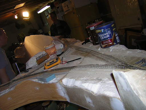
More On30 module progress was achieved during this past weekend. Trackwork was re-checked and yet more spikes were added where necessary. The wye, gorge & curve module sets were connected together, and the fascias were cleaned up & primed.
Once the setup was checked for shorts, the Bachmann Davenport travelled over all the trackwork looking for areas where short-wheelbase locos might encounter problems with electrical pickup. Reversing the engine through the wye was tested several times.
To the best of all of our recollections, the outside-framed consolidation and the C-16 both successfully negotiated the least smoothly aligned leg of the wye (which still needs a short siding installed) during the Christmas Train Show. We have noted, however, that it is unlikely that the Forney or the K-27 will be able to travel over all of the trackwork in its current state.
Scenic treatment prior to the show will consist of mis-tinted acrylic paint covered in sand and/or sanded grout. Some coniferous trees have been purchased from MountainView Depot to "spruce" up the landscape a bit.
We are still debating the final fascia colour. The intent is to provide a surface that will present a uniform appearance, resist fingerprints & other marks, and keep the eye focused on the scene rather than the benchwork. We have it narrowed the choices down to a few very dark tones but are not certain whether a bluish, greenish, or neutral cast will be the best looking in the end.
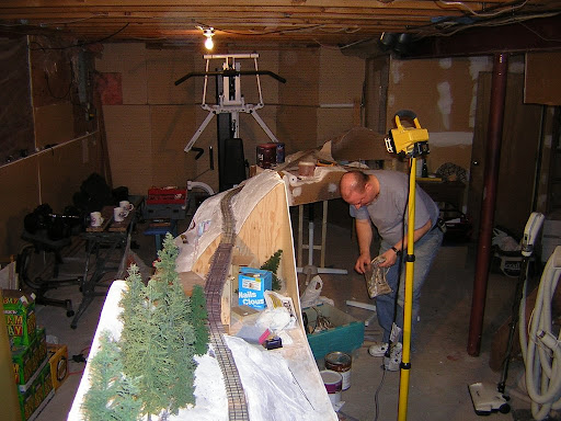
More contour forms, rockwork and trestle bents need to be installed on the gorge set, the loop portion needs additional cleanup, and Whisky Creek definitely requires finishing and a new bridge deck but, we are probably doing OK considering how infrequently we manage to get together for these work sessions.
Once the setup was checked for shorts, the Bachmann Davenport travelled over all the trackwork looking for areas where short-wheelbase locos might encounter problems with electrical pickup. Reversing the engine through the wye was tested several times.
To the best of all of our recollections, the outside-framed consolidation and the C-16 both successfully negotiated the least smoothly aligned leg of the wye (which still needs a short siding installed) during the Christmas Train Show. We have noted, however, that it is unlikely that the Forney or the K-27 will be able to travel over all of the trackwork in its current state.
Scenic treatment prior to the show will consist of mis-tinted acrylic paint covered in sand and/or sanded grout. Some coniferous trees have been purchased from MountainView Depot to "spruce" up the landscape a bit.
We are still debating the final fascia colour. The intent is to provide a surface that will present a uniform appearance, resist fingerprints & other marks, and keep the eye focused on the scene rather than the benchwork. We have it narrowed the choices down to a few very dark tones but are not certain whether a bluish, greenish, or neutral cast will be the best looking in the end.
More contour forms, rockwork and trestle bents need to be installed on the gorge set, the loop portion needs additional cleanup, and Whisky Creek definitely requires finishing and a new bridge deck but, we are probably doing OK considering how infrequently we manage to get together for these work sessions.
3.21.2007
FreeMoS

This years S scale modular display at Copetown, Ontario was again very well received.
Soundtraxx DSD and Tsunami equipped Moguls and 10-wheelers were pacing back and forth along the rails to the delight of the attendees, some of whom remembered the presence of steam on local rails. Even a Pacific travelled around the trackage for a while. Pete arranged a photo of it crossing Andy's causeway module.
Subscribe to:
Posts (Atom)